Wednesday, October 30, 2013

Section 45A – Test Trim and Adjust Potentiometers

This afternoon I began testing the electrical system .  I charged the battery overnight and today it showed 13.4 Volts on the multimeter.  First I removed the upper cowl so I could hook up the battery ground cable.  I also removed the upper fuselage skin.  I turned on the master switch and the Dynon screen lit up and the fuel pump began to hammer.  I pulled the fuel pump fuse to shut off the fuel pump.  
I then I pushed the trim switch on the instrument panel.  Nothing happened with the 
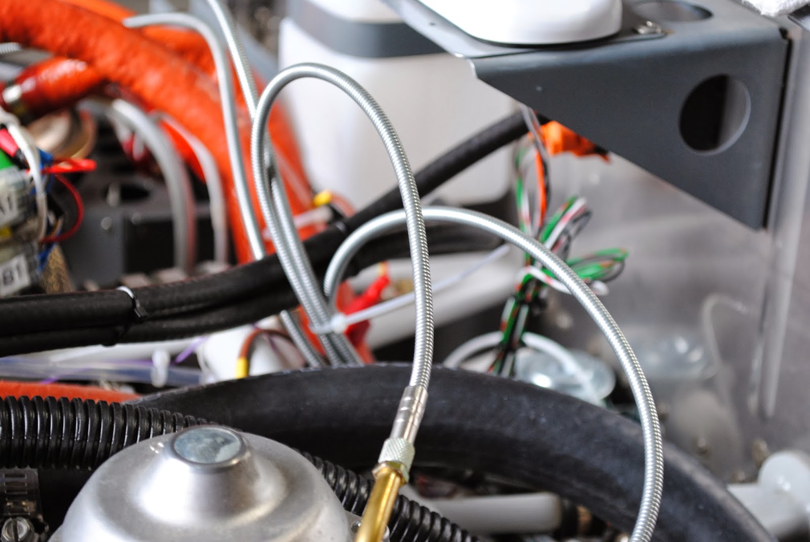
trim.  I went to the rear of the airplane and looked at the trim motor connection.  I did the upgrade several months ago so the connection is a Molex mini-pin block.  I am not sure the pins are making connection in the block.  I removed the block from the servo tray and pulled it apart.  Looking inside it appears the block housing is pushing the pins back so they are not making contact.
Because I am not happy with the way the pins were crimped and because it appears the connection is not working I decided to remove the Molex block and replace it.  I can order a new block and pins from Van’s, but first I want to see if the trim servo is working at all.  I cut the wires and stripped the ends.  Using test leads and a 12 Volt battery I checked to be certain the servo motor is functioning.  It is.  I stripped all of the wire ends and connected them together with test leads.  I repeated the early exercise.  I turned on the master switch and then attempted to activate the trim.  No Joy!
By turning the switches on the panel on and off I discovered some things that don’t seem to be quite right.  Of course the wings are not hooked up so there is no way of knowing if the lights are working.  I will need to have my grandsons help me install the wings so I can test the lights.  I did notice that when I turn on the NAV/STROBE switch the cockpit light and the autopilot indicator light on the instrument panel both illuminate.  They do not illuminate when I turn on only the NAV switch.  That makes sense to me because you would most likely use the strobes at night and the cockpit light would be on at that time.  I am concerned that the autopilot indicator comes on with the NAV/STROBE switch.  It does not illuminate with the autopilot switch.  I thought it would. The SkyView seems to be functioning.  The spar pin indicator is green.  To check it out I moved one of the spar pins and the red warning light next to the starter illuminated and at the same time the spar indicator on the SkyView turned red. I pushed the nose of the airplane out the hangar door and it picked up the GPS signal.  Things seem to be working on the SKkyView, but no trim (the vertical trim indicator on the SkyView screen is grayed) and an autopilot light that seems to illuminate with the wrong switch.  I pulled the radio forward so I can see the wiring underneath. I attempted to call Van’s Support but their lines were busy.  I sent them an email identifying the problem.  I will wait for their answer.  This is most frustrating.  I didn’t get started on the potentiometer adjustments.  I have a thought that maybe the trim problem could be the trim potentiometer is out of adjustment.  No, it couldn’t be that simple.  We’ll see what Support has to offer.

Tuesday, October 29, 2013

Reinstall Prop and Cowling

Today I finished reinstalling the propeller and reinstalled the engine cowling.  I started by installing prop blades and adjustment fixture and the front half of the hub.  At that point I realized the tape was still on the prop blades.

I attempted to remove the tape but was not very successful.  I realized as I removed the tape it also removed the paper label on the backside if each blade.  I removed he front spinner support and the forward hub half and the blades.  I removed the rest of the tape and the paper labels and reinstalled the blades one more time.  I also reinstalled the spinner.
I installed the cowling.  It is a real challenge to get the oil cooler hooked onto the lower cowling.  If it is not in just the right position it will not engage the guide cones.  I finally got it engaged correctly and installed the lower cowling.  The upper cowling was next.  It all seems to fit together pretty well.  I also plugged in the battery charger.  I am planning to do the control module adjustments in the next few days and the battery needs to be fully charged.
I also put together the fuel line modification.  I assembled the parts to install a quick drain under the fuel tank.  After the air worthiness certificate has been issued I will install this with a modified access cover.

Monday, October 28, 2013

Engine Controls

Today I installed the engine controls.  I started by installing the throttle control in the instrument panel.  I routed the control cables through the grommet in the firewall and separated them with the longer control cable on the left.  I then installed the choke control.  I put the cables through the instrument panel.  I pushed them through the grommet and then realized I had not installed the locking nut and washer on the back of the control handle.  I had to pull the cables back out of the grommet (no easy task) and put the lock washer and nut on the cables, and then back through the grommet.  Of course all of this unseated the grommet in the firewall and I had a difficult time getting it back into the hole with all of the cables going through it.  After a lot of pushing and pulling I finally got it in place.  Also, though it does not show in the photo, the extra 5 amp fuse I ordered arrived and I have installed the missing fuse for the fuel pump in the fuse block. 
With the cables through the firewall I installed the cushioned clamps to the engine mount to secure the cables in place.   Next I began routing and connecting the cables to the carburetors.  I routed the choke cables to each carburetor and then seated them in the tubes. I then separated the throttle control cables and routed them to each carburetor.  I removed the threaded connections that came on the carburetors and using the lock nuts and washers installed the cables.  I threaded the throttle control cables through the CT-00101 stop nuts however I discovered that I would not be able to tighten the set screw in the stop nuts with the tools I have.  I had to go an purchase a T5 mini-Torx tool to do that.
I installed the cables with the appropriate locking nuts and washers and tightened the set screws.  I cut-off the excess cable lengths and applied ¼” long piece of white shrink tubing to the ends.  The engine controls are now installed.
I decided to start re-installing the prop and spinner.  I was able to install the spinner back plate and the propeller hub base mount to the flange.  I torqued the bolts in place.  I had to quit for the day so I will finish the prop re-install tomorrow.

Friday, October 25, 2013

Engine Cowling

Today I worked on the engine cowling.  I sanded the filler I put on the right lower rear edge of the upper cowling half.  It worked very well and I am pleased with the fit.  I also sanded the front area of the upper cowling behind the prop .  I then continued to install the heat shield material.
There was just enough heat shield material to complete the job.  I took a picture of the completed heat shield.  I reinstalled the lower cowling half and final drilled the holes for the screws attaching the cowl to the lower fuselage attach plates.  
Next I installed the 2.5" scat tube between the lower cowl air inlet and the engine cooling shroud.
My next task was to install the oil cooler and the associated lines in the oil system.  It took a lot of effort to get the oil hoses behind and under the engine.  I ended up weaving them through the engine compartment maze and removing them several times.  Finally I was satisfied with the placement of the lines and reinstalled the lower cowl.  It all seem to fit together nicely.
I reinstalled the lower cowl and captured the oil cooler with the guide cones.  After a few minor adjustments to the oil hoses it all seems to fit.
I noticed an edge and corner of the compression seal was not holding properly.  I applied a small amount of clear silicone and clamped them back in place.  That is all for today.

Thursday, October 24, 2013

Spinner, Spinner Back Plate and Cowling

This afternoon I worked on the cowling and the spinner and spinner back plate.  I sanded down  the fill material I put on the right lower rear edge of the upper cowling.  I worked reasonably well, but I discovered I need to add additional resin-flox mixture to build up that edge of the cowling.  I mixed another small batch of resin and mixed in some flox.  I applied it to the right rear lower edge of the upper cowling.  I will sand it off tomorrow after it cures.
I cut a piece of ½" MDF 11" square.  I used some spray glue and adhered some 80 grit sand paper to the surface.  I bolted a 6" square piece of ½" MDF to the spinner back plate.  I put a 5/16" bolt through the center and put it in the drill press chuck.  It does not fit.  The edge of the spinner back plate touches the vertical post of the drill press.  That whole idea was over in a heartbeat.  I then thought I would try sanding the spinner back plate by rubbing it over the 80 grit sand paper.  I discovered it worked.  It took about 20 minutes of work, but I was able to sand almost 1/16" off of the rear of the back plate lip.  I attached the spinner and using the sand paper I sanded off the fiberglass spinner to match the back plate.  I deburred the edge of the spinner back plate on the Scotch Brite wheel.
After my success with the spinner and spinner back plate I decided to start installing the reflective heat shield inside of the lower cowling.  I used some flimsy to make patterns of the size and shape mneeded to cut out the heat shield material.

I will work on the heat shield again tomorrow.

Wednesday, October 23, 2013

Cooling Duct and Cowling

Today I made significant progress towards completing the cooling duct and cowling.  I removed the clamps from the transition seal.  It is securely attached to the duct transition.  I sanded all of the areas filled with the resin-flox mixture.  Reinstalled the cowling and determined where I need to re-drill attachment holes.  Removed the lower cowling closeout and attached it to the cowling and drilled out the holes filled with the resin-flox mixture yesterday.
I also sanded the front  of the upper cowling.  The prop spinner back plate is just too close to the upper cowling. After reinstalling the upper and lower cowling halves I decided I need to shave 1/16th of an inch off of the back lip of the spinner back plate.  Accordingly I removed the spinner and prop once again.
In addition of removing the prop  I also used epoxy resin to attach the duct seal label to the cooling duct.
Yesterday I filled a section of the upper cowling right aft lower corner with some of the resin-flox mixture.  It worked really well so I decided to fill a little bit more of the aft edge of the upper cowling.  Tomorrow I will sand it off and check again for the fit.  I am also going to make a jig that I can attach to the drill press to sand down the aft lip of the spinner back plate.

Tuesday, October 22, 2013

Cooling System Nearing Completion

This afternoon I removed the cowling.  I inspected the fiberglass and it all looks good to me.  The connection of the duct to the inside of the lower cowl looks fine.  The layers of glass on top of the intake oval opening and inside of the cooling duct transition look good.
I mixed a small bath of epoxy resin and flox.  I removed the clecoes and filled the holes with the resin flox mixture.  I also filled the open at the topof the air intake oval.  I filled the holes in the bottom of the lower cowling where it attaches to the lower fuselage.  I am going to put a layer of fiberglass on the inside of these attachment points and then redrill the holes.  I also filled 2-ea of the holes in the bottom of the cowling where it attaches to the cowl bottom close out.  I will redrill these holes when the resin flox mixture is set.
The last thing I did today was install the compression seal around the cooling duct transition.  I sanded the outer edge of the transition and then cleaned it off with MEK.  I brought a tube of clear silicone sealant from my shop at home.  I cut the compression seal pieces to length.  I also cut some pieces of scrap wood strips to length so I could us them to clamp the seal to the transition.  I applied the silicone to the tab on the compression seal and then attached them to the perimeter of the transition duct.  I used ‘C’ clamps and Vise Grip clamps to hold the compression seal in place while the silicone caulk sets up.  I also cut a small strip of aluminum to support and hold the compression seal as it went around the rounded corner of the transition duct.  I will leave it this way until I return to the hangar tomorrow afternoon.