Tuesday, April 27, 2010

Electrical Connectors for Trim Servo


I installed the electrical connectors for the trim servo.  I had to order a new connector to replace the female connector I ruined.  The new connectors arrived yesterday.

I cut of the end of the wire bundle.  I stripped the ends of the individual wires and installed the connectors.

Wednesday, April 21, 2010

Installed and Tested the Trim Servo Assembly

I installed the Anti Servo Trim Tabs on the Stabilator. I cut the hinge wires to length and put a 90 degree bend at the end of the wires as shown in the plans. I also ground a dull point on the long ends. I then attached the AST's. I will safety wire them at the final assembly.
 Next I attached the pushrod end bearing to the AST's.  I installed the Trim Servo Tray to the fuselage bulkhead as directed. 

After the servo trim tray was installed I connected the 12 volt battery to the white wires and advanced the servo motor to the stops.  I checked the Stabilator travel and assured it traveled freely to the stops.
I reversed the polarity of the battery and ran the motor to the full travel in the opposite direction.  All went well.

I then checked the Stabilator travel and it moves freely to the stops.

Tuesday, April 20, 2010

Fit Stabilator toTailcone


Today I finished assembling the trim servo tray.  I installed the bearing at the end of the pushrod and attached  the servo to the clevis.
  
It is now ready to be tested on the airframe.


I attached the counterbalance arm to the stabilator and maneuvered it into the tailcone.  I lined up the stabilator with the bearing brackets and inserted the bolts to temporarily hold the stabilator in place.  I used 3/16" dowels to hold the counterbalance arm in place.

I am ready to install the trim servo tray and perform the required tests.

I fabricated a 12 volt battery for the test using 8-each 1.5 volt 'D' batteries and a battery pack from Radio Shack.  The servo motor will draw only 1 amp so this temporary battery is adequate for the test.


Monday, April 19, 2010

Finished Servo Tray


I clecoed the pushrod to the clevis plates and installed the bolts and washers and attached the clevis and link as directed.
 
 
I match drilled the clevis plates to the pushrod.  I also inserted the treaded insert into the end of the pushrod and match drilled the holes in the end of the pushrod.
 I stripped the ends of the servo wires and crimped the connections.  I then inserted the wire bundle through the cushioned clamp and attached it to the servo tray.
 
Next I riveted the clevis plates to the pushrod and riveted the threaded insert to the end of the pushrod.

Thursday, April 15, 2010

Servo Tray Assembly Continues

This morning I primed the parts for the trim servo tray. The weather was good so I rolled the priming station outside and took advantage of the mild temperatures.


I used the countersink to prep for the platenut rivets and then riveted the platenut in place. I also riveted the doublers to the sides of the tray.


I clecoed then match and final drilled the #27 holes through the servo and retainers.


I then installed the nuts and screws.

Wednesday, April 14, 2010

Prepared Parts for Trim Servo Tray


I worked on the stabilator to make sure the counter weight arm will fit and the bolts will go through the holes.  I had to use the angle drill to final drill the holes for the AN3-14A bolts.

I separated , deburred, polished, cut and got ready the parts for the trim tab motor assembly.
 

Tuesday, April 13, 2010

Intalled Vert Stab and Rudder


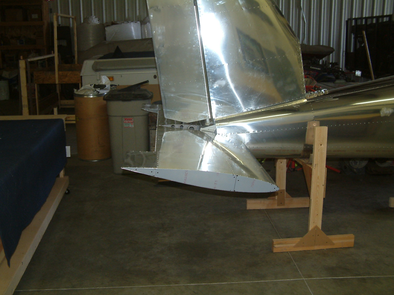
I started the installation of the empennage. I first attached the vertical stabilizer using the called out bolts and the lower hinge assembly. I also installed 3-bolts on the front of the stabilizer. One of the AN3-4A bolts was stripped installing the stabilator brackets so I have ordered some additional bolts. I will install the last bolt after they arrive. Next I installed the rudder. Before doing so I used some Titebond instant glue to glue the washers in place. I glued them per the initial trial fit of the rudder.

After gluing the washers in place I used a sharpened 3/16" dowel to line up the holes. I was able to get the bolts in place and test the swing of the rudder. It seemed to be too close to the vertical stabilizer at the upper left edge.

I removed the rudder and using my angle grinder and a 3M Scotch Brite disk I ground off about 1/16" of the upper edge. The rudder now fits very well. The next step was to install the fiberglass fairings on top of the rudder and the vertical stabilizer. I first fitted the rudder fairing. To do so I had to remove material at the bottom of the fairing so it would fit into the opening. I clamped the fairing to the work bench and used my Dremmel tool to cut the fiberglass. It made a good clean cut. I then fitted the fairing to the top of the rudder and drilled and clecoed it in place.

I then reinstalled the rudder to the vertical stabilizer and began to fit the fairing to the vert stab. It took a bit of cutting, sanding and reshaping but I was able to get the two fairings to fit well together. I then drilled, clecoed and riveted the vertical stabilizer faring in place.


Monday, April 12, 2010

Tailcone Completed


Today I finished pulling the rivets on the tailcone.  I riveted the upper skin stiffener and the forward skin rib in place and pulled the rest of the rivets on the upper skin.  The tailcone is complete to this point.

Friday, April 9, 2010

Forward Skin Attachement Rib

This morning I dimpled the forward skin rib for the #8 screws and the platenuts. I riveted the platenuts and clecoed the forward skin rib to the top of the fuselage.  I clecoed the stiffener to the inside surface of the upper skin.
The upper skin is now ready to rivet.

Thursday, April 8, 2010

Cleco Top Skin on Tailcone

I riveted the upper right corner skin.  I then removed the blue film from the top skin and clecoed it in place.


The end of the top skin did not lay correctly and I had to add some additional break for the last 24". 


All of the holes lined up perfectly and the skins look good.


Monday, April 5, 2010

Installed LP4-4 Rivets

The LP4-4 rivets came in over the weekend so I installed them in the fuselage bulkhead this morning. It took a couple of minutes.

Saturday, April 3, 2010

Rivet Upper Left Corner Skin


Today I took Arlene and our daughter Kerri and her family to the shop to see the progress of the build. In addition to them were Grant and their four children, Tim, Cameron, Kaleb and Taylor. They were all very impressed with what they observed. We decided to spend some time and pull a few rivets.  
I lowered the horses 12” to make the tailcone assembly easier to reach. While Grant and Tim (and Kaleb?) held the tailcone I lowered the cross bar on the horses.  
Following the modification to the horses it was decided that we should begin pulling some rivets. I explained the method and procedures and we got started. Arlene was the photo-grapher and the work began with everyone taking a turn. As I supervised the rivets began to be pulled. Before we left the left upper corner skin was riveted in place. We also installed the snap bushing brackets on the rear of the upper corner skins, installed the bushings and pulled the rudder pull string. Even Kerri got into the act and pulled some rivets. We had a good time and the whole gang is looking forward to future work parties.

Friday, April 2, 2010

Installed Left and Right Side Skins


Today I turned the tailcone assembly upright on the horses. With the tailcone in the upright position I installed the static air system. I pulled the special rivets in the left and right side skins.

I attached the 1/8” plastic tubing to the right side rivet and sealed it in place with clear RTV silicone. I ran the tubing along the inside edge of the fuselage frame and secured it loosely with wire ties. I installed the plastic ‘T’ fitting and ran a short piece of tubing to the left rivet, securing it with RTV. I attached the ¼” poly tubing to the ‘T’ fitting over a ¼” piece of plastic tubing. I ran the ¼” poly tubing along the fuselage frame to the ‘J’ stiffener on the left side skin and ran it to the front of the tailcone and taped it to the floor.

I removed the blue film from the right and left upper corner skin and clecoed them in place.

Thursday, April 1, 2010

Left and Right Side Skins


I pulled the blue film off of the left side skin and clecoed it to the frames and lower corner skin. I clecoed the skins to the frame and the lower corner skins. I riveted the skins to the frames, to each other and to the fuselage bulkhead.

I then pulled the WH-P30 trim control wire through the J stiffener and wire-tied it in place. I taped the coil of wire to the floor of the tailcone as instructed.

I then pulled a sting from the front of the tailcone through the frames and trough the top stabilator pull hole and back trough the bottom stabilator control hole. I taped the ends of the string to the floor of the tailcone.