Friday, July 29, 2011

Covers and Plates Continued


I removed the blue vinyl film from the covers and plates and deburred the edges.  I also dimpled the 5-holes in the rear baggage area floor that will be under the fuel tank.  There are 5-flat head screws that secure the floor under the fuel tank.
Next I turned my attention to the canopy section.  I final drilled the holes in the ends of the gas struts that will support the canopy in the open-up position.  Next I am going to have to start working on the canopy itself.  This should be fun and interesting.


Thursday, July 28, 2011

Covers and Plates


This evening I gathered all of the covers and plates for inside of the fuselage.   I dimpled the seat floor cover that is installed under the flap handle.  I also installed the nutplates.  I set the covers and plates in the locations in which they are to be installed.

Wednesday, July 27, 2011

Rudder Pedal Closeout & Anti-Abrasion Strip

 
This evening I installed the rudder closeout pieces.  It was a real pain to get into the fuselage to install these parts at the top of the tunnel.  They attach to the tunnel walls with 2-#8 screws and nuts.  Then, there is a #8 screw that goes into a nutplate on the edge of the engine compartment shelf.  I attempted to get to the space by standing on a step ladder.  I finally turned the fuselage on its side so I could reach in and put in the parts and fasteners.  I am beginning to become pretty proficient at turning the fuselage on its side.  I just need to make sure it is on the right side and that the flaperon control is not over the work table.  The OAT probe is on the left side and would be damaged if I were to roll the fuselage on its left side.


After installing the rudder closeouts I decided to put the anti-abrasion strip on the mid-fuselage brace.  I marked one end at 5/16" and put a line ¾" from the aft edge of the brace.  Then after removing the paper from the adhesive side of the strip I very carefully lined it up with the pencil line and smoothed it out on the mid-fuselage brace.  I worked out well and looks great.  This strip is to prevent the seat backs from damaging the finish on the mid-fuselage brace.
 
I rolled the fuselage upright and I am now ready for the next step.

Tuesday, July 26, 2011

Shoulder Harness Cable & Rudder Pedal Closeout

 
This evening I installed the cables for the Shoulder Harnesses.  These cables attach to the straps at the upper fuselage at the rear baggage bulkhead.  There are 2-cables, one for the pilot on the left side and one for the co-pilot (passenger) on the right side.
 
I then prepared the rudder pedal closeout pieces.  I separated them and removed the blue vinyl film.  Next I deburred the edges and dimpled the holes for the nutplate rivets.  I also dimpled the nutplates.  I primed the pieces and riveted the nutplates as indicated.  
They can now be installed to closeout the space aft of the rudder pedals at the top of the forward tunnel and the engine compartment shelf forward of the instrument shelf.

Saturday, July 23, 2011

Control Surfaces & Control Cables

Today is a rare Saturday when I am not working at the Draper Temple.  Because of this I took advantage of the day and spent a good amount of time on the airplane.  As I was working I had to chuckle a couple of times when some young boys went by on the sidewalk out front and I heard them say to each other, "did you see that airplane?"  How cool.  It reminds me of when I was a little boy and enthralled by the airplanes I was always around with my Dad.

 
Today I started by installing the pulleys in the pulley bracket.  I ordered a new tool from Sears so I could final drill the holes in the bracket.  The tool was to be delivered on Friday.  Friday morning I received an email from Sears telling me they had refunded my returned tool.  I guess they didn't have one to ship so they just reversed by order.  Oh well, I can now chalk up one more reason for thinking the Sears Company is staffed by idiots!  Using a ¼" drill bit and a pair of small vise grips I was able to twist the drill thru the holes and open them up to the right diameter.  I installed the pulleys and was ready to move on.
 
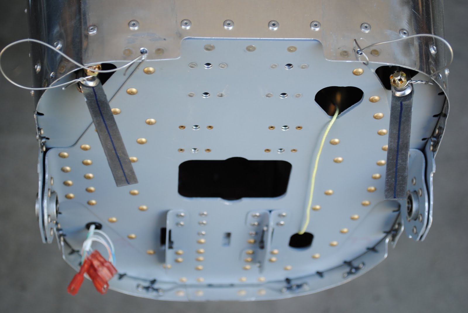
I pulled the stabilator cables thru the rear bulkhead and safety wired them so they would not be pulled back as I connected them under the fuel tank floor.  All of the cables are now in the fuselage and thru the rear bulkhead.
 
Next I installed the vertical stabilizer and rudder so I could mark and cut the rudder control links.  To do so I moved the wings out onto the driveway and turned the fuselage sideways in the garage.
The instructions say to center the rudder and clamp the cable links to the rudder control horns.  To be sure the rudder is centered and remained centered I clamped to aluminum yard sticks to the tail cone so I could make sure the rudder is centered.
After clamping the cable links to the rudder control horns and making sure the rudder was centered I marked the links.  I removed the links from the cables and took them into the shop. Using the links as guides I marked them for the length and to drill the holes.  I lined up 2-links and installed an AN3 bolt thru the hole then clamped them together.  Using the drill press I drilled a #30 hole thru the links and then final drilled them with a #12 bit.  I did the same with the other set of cable links.  Next, I clamped them in the vise and using a hack saw, but them to length.  One set of links is shorter than the other.  I used the bench grinder to round the ends of the links and then cleaned them up with the Scotch Brite wheel.  I then installed them on the rudder control cables as instructed.  I then installed the links to the rudder pedal arms.  I had to turn the fuselage on its side once again in order to reach the rudder pedal arms.  I just could not reach them otherwise.
 
Next I temporarily installed the horizontal stabilator.  
 In order to be able to install the barrel connectors on the stabilator cables I put stings on the ends of the cables.  I also put strings on the ends of the rudder cables.  They can now be retrieved if they are inadvertently pulled thru the rear bulkhead.  With the fuselage on its side I was able to reach thru the inspection holes in the bottom of the fuselage and pull the stabilator cables together.  I installed the brass barrel (threaded connector) onto one of the cable ends.  I then attempted to start the other end of the cable to the opposite side of the barrel.  Of course the worst thing that could happen did.  The barrel slipped out of my fingers and fell thru the lightening holes in the longitudinal ribs.  It ended up out of sight.  I could not get my hands and arms far enough through the holes to be able to feel the barrel.  I turned the fuselage back upright and rolled it over the other way to see if I could get the barrel to roll out of the space it was in.  No dice!  I spread some packing pads on the floor and laying on my back I attempted to find the part.  The barrel is made of brass so I could not use my magnet tool to retrieve it out of the space.  Finally, by tapping the aluminum skin on the bottom of the fuselage I was able to locate the barrel.  It was on the right side of the fuselage in the small space behind the landing gear attachment point.  There is a small hole into the space in the landing gear attachment location.  By using my small inspection mirror and by shining a small flashlight into the space I was able to see the barrel.  It was just out of reach inside the narrow space at the right bottom edge under the wing.  I considered cutting a hole in the skin to retrieve the part.  Of course that would necessitate a repair and that did not sound like something I would like to do.
 
I continued to try to get to the part.  I used masking tape to tape the flashlight to the adjacent ribs so it would shine into the space.  I then taped the inspection mirror in place so I could observe the barrel without holding these tools.  Next I used my claw tool to reach thru the small hole while looking thru the mirror.  After several unsuccessful attempts I was able to grab the part with the little claw.  As I attempted to pull it out it slipped and fell back into the space.  RATS!!  I re-taped the light and mirror so I could see the part and tried again.  This time, after another untold number of attempts I was able to grab the part and with a lot of gentle maneuvering I was able to pull the part out of the space.  I installed the 2nd barrel into the stabilizer control cables.  Because this is only a temporary installation of the stabilator I will have to adjust the cables to the proper tension after the stabilator is permanently installed.  I removed the stabilator and vertical stab and returned everything to its storage space.  Next I start on the canopy.

Monday, July 18, 2011

Stabilator Cables


This evening I stared the installation of the stabilator cables.  Once again, these are interesting cables to install.  They consist of 2-lengths of cables which are connected below the fuel tank area floor.  I started by installing the aluminum bushing between the stabilator pulley brackets as shown on the drawings.  Next I cut the hook off of a shirt hanger and straightening it out.  I bent a small loop on each end.  I tied a string to one  end and pushed it from the tailcone area through the bulkheads.  By holding and twisting the hanger just right I was able to get it to go through the correct holes in the bulkheads.  I attached one of the short stabilator cables to the end of the hanger and pulled it to the area below the fuel tank.  I attached the spade end of the cable to the appropriate attachment point on the control column.  I then followed the same procedure to pull the second short cable into place.  I have no idea why I was successful at getting the cables through the right holes in the bulkheads.  I confirmed they are in the right place by using a small inspection mirror to look under the floor panel.  I will be able to better confirm their location when I put the fuselage on sawhorses so I can get underneath and look through the inspection holes in the bottom of the airplane.
 
I next attempted to install the pulleys for the stabilator cables in the pulley bracket.  Unfortunately, the AN4 bolt will not go through the holes in the bracket.  I will need to use a 90o angle drill attachment with a stubby bit to final drill the ¼" holes in the bracket before I can install the pulleys.
I ended the evening by marking center lines on the rudder cable attachment plates.  I will install the rudder on Saturday, then clamp, mark and drill the attachment plates.


Friday, July 15, 2011

Rudder Pedal Stop

This afternoon I fabricated the rudder pedal stop.  The stop is made from some of the shipping crate materials.  I used my table saw to cut out the sides and middle spacer then screwed and glued the pieces together.  It is a pretty simple device, but it effectively locks the rudder pedals in place so the cables can be attached to the rudder horns and the correct length established.
 
I also attached the rudder cable attachment plates to the fork end of the rudder cables.  To do so I removed the rods I had safety wired to the cables.  I attached the connection plates and then attached a piece of safety wire to each cable and looped it thru a screw hole in the tailcone so the cables cannot be pulled back thru the openings in the rear bulkhead.  I then set the rudder stop block in place in the cockpit.  I am ready to attach the vertical stabilizer and rudder and prepare the attachment plates for final assembly of the rudder controls.