Friday, September 27, 2013

Cooling System Installation Continues

Today I installed the radiator, hoses and started the installation of the cabin heat control knob.  I installed the radiator to the firewall and cooler box frame.  I bolted it in place and then installed the face frame seal and caulked it in place.
I installed the radiator input and output hoses.  I attached them to the radiator, the expansion tank and the outlet at the rear of the engine.  I clamped the lower output hose to the nose gear with a cushioned clamp as shown in the drawings.
I installed the cabin heat control knob on the instrument panel and routed the cable through the firewall grommet and down through the engine compartment.  I begin installing the cushioned clamps to hold the cable to the engine mount tubing.  It is going to be very difficult to install the cushioned clamps to the tubing on the right side of the engine.  I have the clamps in place and a bolt through the clamps but I am having a hard time getting a nut started.  I had to quit for the day, but I  will be back on Monday!

Wednesday, September 25, 2013

Cooling System Installation Continues

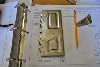
Today I opened the cooler box door and found a problem with the RTV gasket.  It was not cured and the RTV stuck to the firewall.  I put automotive wax on the firewall but apparently that was not the correct wax.  A small section of the gasket came stuck to the door but the majority of it didn't.  I cleaned the RTV from the firewall and the door and started over.  
I went to the Smith's market on 90th South and purchased some paraffin wax.  I put a good coating of wax on the firewall and reapplied RTV tot eh cooler box door.  I reinstalled the door on the cooler box hinge and closed it, holding it shut with a piece of safety wire.  I tried to make the bead of RTV smaller in hopes it will create a gasket but not be too thick.  Hopefully by tomorrow it will be cured.
Before reinstalling the cooler box door I fitted the radiator to the firewall and cooler box face frame.  I enlarged the holes in the radiator tabs and elongated them so it fits properly.  I also prepared the Seal Face for installation on the radiator by removing the blue vinyl film and deburring the edges.  I will install the radiator and seal face tomorrow.

Tuesday, September 24, 2013

Cooling System Continues

Today I continued to work on the cooling system.  I put some wax on the firewall area behind the cooler box door.  I scuffed the edges of the aft side of the cooler box door and applied a bead of red high heat RTV around the edge of the door.  I used a piece of safety wire to hold the door closed so the RTV will form a gasket around the edge of the cooler box door.
Next I installed the oil tank.  I installed the large clamps on the oil tank mount.  I placed the tank in the mount and tightened the clamps.
I cut a 1- ½" piece of hose to make the oil vent interconnect.  I then formed the oil vent tube from some .062x3/8 aluminum tubing.  The tubing goes from the vent port on the oil tank behind the engine mount and down past the gascolator.  I inserted the end into the oil vent interconnect and installed a cushioned clamp around the tube and attached it to the right gascolator bolt.
I attached the overflow bottle to the firewall by putting a smear of gray RTV on the ribs behind the bottle.  I attached the overflow bottle with the clamp painted last Friday.
Unfortunately I am unable to find the hose material to make the overflow bottle hose.  It connects the overflow bottle to the expansion tank.  I called Van's and was told they supplied a 42" piece of the hose with the engine kit.  I must have misplaced it somewhere.  I ordered a new piece of hose.  It is being sent by priority mail.  I will continue to work on the things I can while waiting for the hose to arrive.

Monday, September 23, 2013

Started Cooling System Installation

The first thing I did was cut the radiator cooling hoses to length.  The input hose is 30” long and the output hose is 20” long.  There is a short piece of rubber hose left which will be used in a future step.  Next I inserted the springs into the hoses.  That was a chore, but by holding the end of the spring with a pair of pliers I was able to twist them into place. 
Next I cut the stainless steel hinges to length to make the 2-halves of the cooler box hinge.  Using the hinge pin I fabricated the pin for the cooler box door.  I clamped the hinge to the cooler box door and then match drilled the hinge per the door hole layout.  I dimpled the door and used the #40 microstop to countersink the hinge.  I riveted the hinge to the door.  Next I dimpled the door for the door bracket.  I used the microstop to countersink the bracket and then rivet the door and bracket together. 
I then clamped the hinge half to the cooler box face frame and match drilled the hinge.  
I removed and deburred the hinge and then riveted the face frame and hinge half to the lower firewall.
I riveted the upper and lower cooler box ribs to the face frame and firewall.
I installed the cooler box door and safety wired the hinge pin to the upper rib.

Friday, September 20, 2013

Finalize Spinner Installation and Install Exhaust

Today I took the time to finalize the installation of the prop spinner.  I installed all of the screws and nylon washers on the spinner.  I then determined I would try some things I have been considering to take the downward slant out of the pitot tube and center it in the prop shaft.  My first thought was to remove the pitot block and put some kind of small wedge between the pitot block and it's mounting location on the engine.  I then determined that unless I somehow reamed the holes in the pitot block a wedge would not cause it to move.  The cap screws mounting it to the engine would keep it from assuming the slope of the wedges.  I then thought maybe if I can remove the block with the pitot tube still installed I could somehow put a slight bend in the pitot tube where it exits the pitot block, just enough to center it in the prop shaft.  I removed the cap screws and using a large screwdriver I tweaked the pitot tube just a little bit.  I reseated the pitot block and discovered the tube has moved up just a little bit.  I tweaked the tube again and voila, it worked.  I reattached the pitot block and a you can see from the photo the pitot tube no longer rests on the prop adjustment fixture,  Success!  I then installed the spinner.
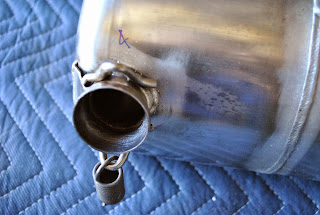
Next I started to install the exhaust system. I removed the yellow plastic cups from the exhaust ports and removed the nuts from the exhaust port studs.  I disassembled the muffler and exhaust pipes be removing the springs.  I put some anti-seize past in the ball joints of the muffler.
I loosely installed the exhaust pipes on the engine and attached the muffler.  I tightened the exhaust port nuts but left them loose enough that I could move the muffler and wiggle it to seat the pipes as instructed. 
re-installed the engine cowling to make sure everything fits properly.  I discovered after all is in place the exhaust system fits just fine but spinner back plate is too close to the upper portion of the cowling.  I will need figure out a way to correct this problem.  It should be 1/16th to 1/8th of an inch from the cowling.  It is more like 1/32nd of an inch away.  I need to get 1/16th of an inch clearance.  I have some ideas I will pursue. 
I removed the cowling and continued with the installation of the exhaust system.  I tightened the exhaust port studs and torqued them in to the correct foot pounds.  I then removed the springs, one by one and filled each spring with red high temp RTV.  I reinstalled each spring and put RTV over the end of the spring at its attachment point as instructed.  It is a red globby mess.
After cleaning up from the red RVT experience I installed the heat probes on the exhaust pipes and connected them to the wiring installed with the fuselage forward wiring harness.  This completes the installation of the exhaust system.  I will start the installation of the cooling system next.
I brought home some of the components for the cooling system.   I primed them and painted them gray so I can begin installing them on the firewall.

Thursday, September 19, 2013

Finish Prop and Spinner

This afternoon I completed the installation of the spinner.  I removed the spinner plate and spinner bulkhead.  I also removed the prop and hub.  I drilled, deburred and countersunk all of the necessary holes in the gap fillers, back-up plates, the spinner and spinner plate and bulkhead.  I riveted the gap fillers to the spinner plate.  I riveted the back-up plates to the gap fillers.  I riveted nut plates to the back-up plates, spinner plate and spinner bulkhead.  I re-installed the prop along with the spinner plates and bulkhead.  I then slid the spinner in place.
I have discovered that the pitot tube is not centered in the prop shaft.  It is a little low and actually rests on the bottom of the opening in the prop adjustment fixture.  I emailed Van’s and was told if the pitot tube is exerting a downward pressure on the spinner bushing it is a problem.  I will need to make some kind of modification to center the pitot tube in the prop shaft.