Monday, April 22, 2013

Install Lower Fuselage Cover at Landing Gear

I finally installed the 2-corner covers at the main landing gear legs on each side of the fuselage.  I cut the pieces apart on the band saw.  I deburred the edges and then riveted them to the fuselage skin on each side below the main gear legs.  I inserted the plastic fill in plugs into the holes drilled in the bottom skin on each side of the fuselage.

Friday, April 19, 2013

Finish Installation of Landing Gear and Fuel Tank

This morning I purchased an extension for the 3/8" ratchet.  This afternoon I was able to torque the AN6 center bolt on the inboard attachment of the left main gear leg.  I then attached the brake line.  I proceeded to install the component for the right main gear leg.  I installed the outboard doubler and wear plates.  
I slipped the gear leg in place and loosely installed the outboard hold down bracket.  I then installed the inboard doubler and wear plates.  I installed the bolts and attached the inboard hold down bracket.  I then tightened all of the bolts sequentially until all bolts were seated properly.  I then torqued all of the bolts to the proper torque per the SB instructions.
I reinstalled the flexible duct in the mid channel by reattaching the cushioned clamps.  I also reinstalled the fuel tank.  I also reinstalled the ELT and the ELT antenna bracket.
The airplane is now sitting back on its own legs.

Thursday, April 18, 2013

Install Wear Plates and Left Main Gear Leg

This afternoon I put a coat of primer on the exposed surfaces of the outboard hold down bracket chamfered edges and the wear plates and doubler plates. 
Next I installed the outboard doubler and wear plates.  I used 2-AN5 bolts as alignment pins and installed the plates with the flat head #10 machine screws with nuts and washers.  I then slipped the gear leg in place and installed the outboard hold down bracket.  I aligned the gear leg and installed the inboard doubler and wear plates and dropped the bolts through the holes.
I sequentially tightened the bolts until they were all snug and then used the torque wrench to tighten them.  I need to purchase an 8" - 3/8" drive extension before I can torque the AN6 nut at the inboard hold down bracket.  After the center AN6 nut and bolt have been tightened I will reinstall the brake line and the left gear main reinstall will be complete.

Wednesday, April 17, 2013

Complete SB 13-4-05 Oil Tank Mount Brackets

This afternoon and evening I completed the painting and installation of the additional rib on the oil tank mount brackets.  I prepped and primed the rib this morning and I applied a coat of finish paint on the rib this afternoon.
I put the rib in place and installed the pulled rivets.  The modification is not complete.

SB 13-4-05 Oil Tank Mount Brackets

Today I received the parts to modify the oil tank mount brackets from Vans.  Vans issued a service bulletin after some cracks were discovered at annual inspections on some aircraft.  A new support rib is to be installed at the bottom of the oil tank mount brackets.  I decided to do the modification now instead of waiting.  This evening I set the new additional rib in place.  I then marked and drilled the oil tank mount brackets.  I will now deburr the edges and prep the rib for primer and paint.  After I have primed and painted the rib I will rivet it into place.

Thursday, April 11, 2013

Drill and Prep Wear Plates

Today I continued to work on the Service Bulletin.  I finished chamfering the corners of the outboard gear attach brackets.  They are now ready to be installed.  I deburred the edges of the outboard doubler plates and the outboard wear plates.  Following the directions in the SB I installed them under the mid-channel along with the drill template above the mid-channel.
I match drilled the #30 holes in the drill template through the mid-channel and the plates below.  I removed the drill template and deburred the holes.  I reinstalled the drill template on the other side and did the same thing.
With the template still in place I final drilled the holes to ¼".  I removed the template, vacuumed up the drill shavings and relocated the drill template back to the other side and final drilled the ¼" holes in that side.  
I then followed the instructions and countersunk the bottom side of each wear plate using the cut off bolt in the drill press as suggested.  It worked very well.  I am now ready to reinstall the landing gear.

Friday, April 5, 2013

Rivet Side Skin Doublers

This afternoon I riveted the side skin doublers and side skin support angles in place.  The first thing I did was get out my big shop vac and cleaned up all of the rivets and drill chips from inside of the fuselage.  They were everywhere.  After vacuuming up the visible debris in the interior area I used some duct tape to attach a piece of flexible conduit to the end of the vacuum hose and vacuumed the debris from the ribs through the lightening holes.  What a process.  When I was finished I started to pull the rivets.  
First I installed the skin support angles with Cherry Max rivets to the mid fuselage channel.  I tapped the spar sleeves back to clear the rivets.  I was a real chore to tap them back into place, but I was able to do so.  I photographed the skin support angles from above.  The photos are not to clear, but they show the angles riveted in place to the channel.


Next I pulled the flush rivets at the bottom edge of the doublers.  All went well.

At this point I pulled the LP4-3 rivets in the field of the skin doublers. 

The last rivets to be pulled were the Cherry Max rivets attaching the sides to the vertical ribs.  All of the rivets for the service bulletin have been pulled.
I then started to chamfer the corners of the gear leg hold brackets.  I marked the corners and used my bench grinder to remove the material.  It is a long, hot process.  I stopped for the evening and will finish tomorrow.

Wednesday, April 3, 2013

Prep For Skin Doublers

This afternoon I started to prep the airplane and the doublers for installation.  I 
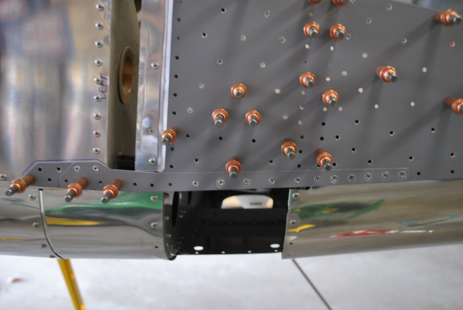
started by marking and drilling the holes in the bottom skin.  This will accommodate a ¼” ratchet extension to make installing and torqueing the bolts a little easier.  The photos are a bit dark but the holes are there.
Next I held the skin doubler to the side of the fuselage and marked its location with a Sharpie.  I used a 1/16” drift punch to punch out the mandrel in all of the rivets to be drilled out.  I then drilled out the rivets on each side of the fuselage.   I clecoed the holes as I drilled them to help keep the skin doubler and the fuselage sides in line.  I also drilled out the rivets holding the side skin support angles attached to the mid fuselage channel.
After drilling out the rivets on the right side of the fuselage I prepped and primed the doubler skins and the side skin support angles.  I deburred the edges and used a Scotch Brite pad and some MEK to clean and prep the surfaces.  I clecoed the primed skin doublers in place on each side of the.  After drilling I removed the skin doubler and deburred the holes and cleaned away any drill chips between the layers of aluminum.
I used the microstop counterskink to prep the small side skin doublers to receive the CS4-4 flush rivets.  I then clecoed the doubler skins in place.  I also clecoed the side skin support angles to the ends of the mid fuselage channels.  I am ready to match drill the side skin support angles and then start pulling the rivets.