Friday, October 19, 2012

Park Brake Valve Mounting Bracket

I completed the park brake mounting bracket.  I bent it to shape and riveted the nutplates in place.  It will be ready when it is time to install the park brake.

Thursday, October 18, 2012

Future Modifications

I worked on 2-future mods for the RV-12.  One is the installation of a parking brake.  I went to MATCO in Bountiful and purchased their PVPV-D park brake valve.  It will be installed in the brake lines going to the control tunnel.  I used the drill template used to make for installing the Skyview changes to make the mounting  bracket.  I drilled the various holes and used the counter sink to prep the bracket for riveting on the nutplates on each end.  I will bend the bracket on our break in the shop at work.  I am planning to remove the cushioned clamp holding the brake lines in the tunnel.  I will use the fastener hole to attach one side of the park brake mounting bracket.  I will need to drill an additional hole for the attachment of the other end.  I have ordered the 45o fittings to connect the poly brake lines on each end of the valve.  I have also order the bolts and nuts to attach the valve body to the mounting bracket. 

I have ordered a universal light cable from McFarlane to control the park brake.  I also ordered a black knob with the words PARK BRAKE.  I have some thoughts about where to install the control on the instrument panel.  I will make the final determination when I am ready to make the installation.
I also put the ends on the 1/16" tubing for the AOA.  They are connected as the wings are installed.  I will drill the wing and install the AOA port after certification.

Monday, October 15, 2012

Aircraft Assembly

This afternoon I stopped at the Sutton's in Eagle Mountain and picked up my grandsons, Cameron and Kaleb.  They agreed to help me assemble 
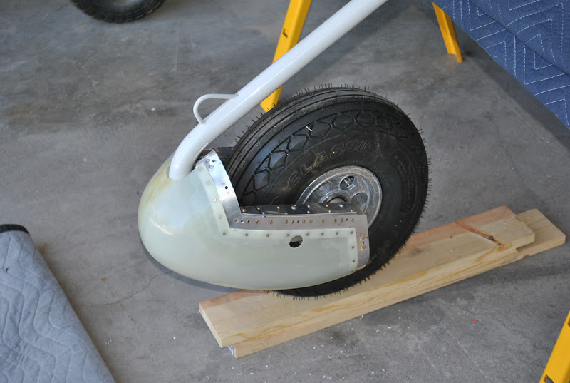
the airplane this afternoon.  We started by installing the wheel pants on all three wheels.
Next we installed the upper fuselage cover over the instrument shelf.  After installing the upper cover we installed the rear window and the turtle deck skins.  These are just clecoed in at this point.  I will permanently install them very soon.

At this point we moved the airplane onto the driveway and began to install the canopy.  We had the canopy in place and lowered it down.  Then just to make sure everything was OK I raised the canopy.  It was actually to get the camera from inside the cockpit and take a photo.  On lifting the canopy, the support arm on the right side hung-up on the edge of the upper fuselage skin.  Lifting the canopy all of the way up bent the edge of the skin up.  We removed the canopy from the airframe and removed the screws holding the skin in place.  With my duck-bill pliers I was able to straighten out the bent edge.  I put a little extra crease along the edge of the skin so when it is installed it will be tighter to the fuselage.  We reinstalled the screws and using a file I smoothed the edge of the skin.  After reinstalling the canopy we confirmed that it goes up and down without any interference.
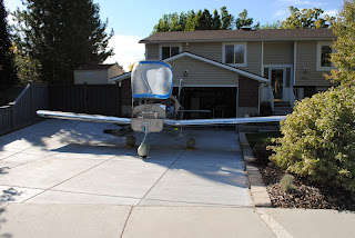
Our next step was to install the wings.  We installed the left wing and then the right wing.  I will need to pull the wings into place when I install them the final time.  Right now it is difficult to install the spar pins without a huge amount of effort.  
Grandma came out to check our progress.
Next we installed the empennage.  We didn't  hook up the control cables, but I know they work.
Grandma came out again and the boys encouraged her to take a turn sitting in the cockpit.  She was laughing and smiling the whole time so I guess she liked it.  I am going to go up to MATCO Mfg in Bountiful and purchase their parking brake valve.  I am planning to install it in the tunnel where the brake lines pass on their way to the center section.  I will buy the valve from MATCO and a actuator cable from McFarlane.  They make one labeled 'PARK BRAKE.'  Of course the park brake will be installed after certification.

Friday, October 12, 2012

Nose Gear Leg Fairing

This afternoon I worked on the nose gear leg fairing.  The epoxy is set under the screws.  I removed the leg fairing and clamped the piano hinge assembly inside with large 'C' clamps. 
Then I started drilling from one end of the hinge and drilled and clecoed each hole on one side of the fairing.  The drilling and clecoing went fairly well.  My drill battery ran down so I installed another battery and continued to drill and cleco while I charged spent battery.  I finished drilling the first side and turned the assembly over and drilled and clecoed the other side.  I removed the clecoes and using my microsink, prepped the holes in the leg fairing for riveting the hinge in place.
I took the fairing into the shop where I had clamped my rivet squeezer in the bench vise.  One by one I inserted and squeezed the rivets attaching the hinge assembly to the leg fairing.  I also located the attachment point for the hinge clamp and drilled a hole for the screw.  
I reinstalled the fairing on the gear leg using the hinge pin and screws to hold it in place.
I reinstalled the wheel pants to make sure the gear leg fairing and the wheel pants had the correct amount of clearance.  I ended up trimming the lower flange of the leg fairing to allow the proper clearance at the top of the wheel pants.  There has been considerable discussion and issuance of SB's concerning the attachment of the main gear legs to the center channel.  It appears I will be working on these attachment points in the very near future.  A statement from Van's dated 10-12-12 leads me to believe I will be removing the gear to make some structural modifications.  It also looks like I will be installing some fuselage skin doublers at the wing roots.  Someone said, once a builder always a builder.  I guess that is true.

Nose Gear Leg Fairing

I started working on the nose gear leg fairing.  I started by cleaning up the excess resin material at the bottom inside edge of the fairing at the joint.  There was no way to make the hinge assemble lay flat in this 'V' because of the excess blobs of resin.  I used the Vixon file and  a sanding block to remove the excess material and made the inside surface flat so the hinge can be installed.
I used the angle grinder with a flat sanding disk and the sanding drum to remove the fiberglass to the scribe lines at the top and lower end of the fairing.  I slipped the fairing over the nose gear leg and clamped it in place.  Using ¾" nuts attached to a piece of string I installed a plumb line and checked to be sure the fairing was lined up properly.  I also drilled the lower flange on the fairing and installed 3-clecos to hold things in place.  I put a strip of masking tape on each side of the fairing and using a framing square I marked the tangent location on each piece of masking tape.  I measured and marked the screw location on each piece of tape then drilled a #30 hole through the fiberglass fairing into the gear leg.  I used an 8/32 tap to tap the holes in the gear leg.  I put a piece of tape around the gear leg covering the drilled and threaded holes.  I rein stalled the fairing over the gear leg.  I mixed some epoxy resin with some glass beads and put eh mixture into a large syringe.  I injected the epoxy mixture through the holes in the fairing to form a puddle of epoxy on the tape on each side of the gear leg.  I then installed wax coated screws to hold the fairing in place while the epoxy sets. 
I then prepped a hinge section for installation inside of the fairing.  I marked each half of the hinge assembly for drilling.  I also fabricated a hinge pin with a 1" section of hinge with a nut plate installed.  I finish the fairing fabrication tomorrow, after the epoxy has completely set.

Tuesday, October 9, 2012

Nose Wheel Fairing

This afternoon I set up the work table in the garage and started to install the nose wheel fairing onn the nose wheel.  I removed the nose wheel and drilled out the ¼" hole to 5/16" and installed the bolts, nuts and washers for the tow bar attachment.  I used the microstop to countersink the rivet holes on top of the wheel fork then riveted the nutplates in place.

re-installed the pants on the nose wheel and checked to be certain the fairing clears the nose wheel strut and the it also clears the tire by at least ½".  I need to start work on the nose gear strut fairing.

Monday, October 8, 2012

Nose Wheel Doublers

This afternoon I installed the doublers on the wheel mounting brackets.  This is because of a Service Bulletin issued by Vans.  Inspections of flying RV-12's has shown cracking of the nose wheel mounting brackets.  This is to correct and prevent that problem.  I installed the aft half of the nose wheel pants and marked the location of the mounting brackets on the rill template.  I removed the aft portion of the pants then clamped and drilled the brackets.
Next I went into the shop and deburred the holes and deburred the edges of the doubler plates.  I attached the doublers to the mounting brackets and drilled all of the #40 rivet holes.  I deburred the holes and then dimpled the interior holes along the edge of the brackets.  I also countersunk the corresponding holes in the doubler plates.  Next I riveted the doublers to the brackets using the rivets provided with the kit.  
I then temporarily put the forward half of the pants on the nose wheel to see how it fits.  It looks good.  I will remove the wheel and install the tow-bar bolts and washers and install the nutplates.

Wednesday, October 3, 2012

Nose Wheel Pants Continue

This afternoon I stopped at Home Depot and purchased some #8/32 screws and nuts.  I set up my work area in the garage and started to work on the nose wheel pants again.  I used my angle drill to match drill the screw attachment hole in the aft half of the pants.  As I match drilled a hole from inside of the pants I installed a #8 screw and nut to hold it in place.  Working hole by hole and screw by screw I was able to complete the task.  I then mixed some epoxy and glass beads to spread between the splice plates and the inside edge of the forward half of the pants.  Per the instructions I put masking tape on the exposed part of the splice plates.  I removed the splice plates and roughed up the exposed edge of the splice plates and the contact area inside of the forward section of the pants.

I spread a thin layer of the epoxy mixture on the splice plates and then clecoed and riveted them to the forward pants.  I then clecoed the support brackets to the splice plates to confirm they fit properly.
Next I riveted them in place along with the required nut plates.  I also attached the drill template to the support brackets.