Thursday, December 27, 2012

Engine Mounting Ring

This afternoon I installed the engine mounting ring on the Rotax.  First, I uncovered the engine and set the cooling shroud in place.  It think it will look good.
I then proceeded to install the engine mounting ring on the engine.  To begin with I removed the front bolts from the engine support angles.  I lifted the rear of the engine and placed a 2x4 block under the crank case.  I then used a small pair of channel locks to remove the 4-spring clamps from the water pump inlet and outlet on the water pump.  After cleaning up the coolant that drained 
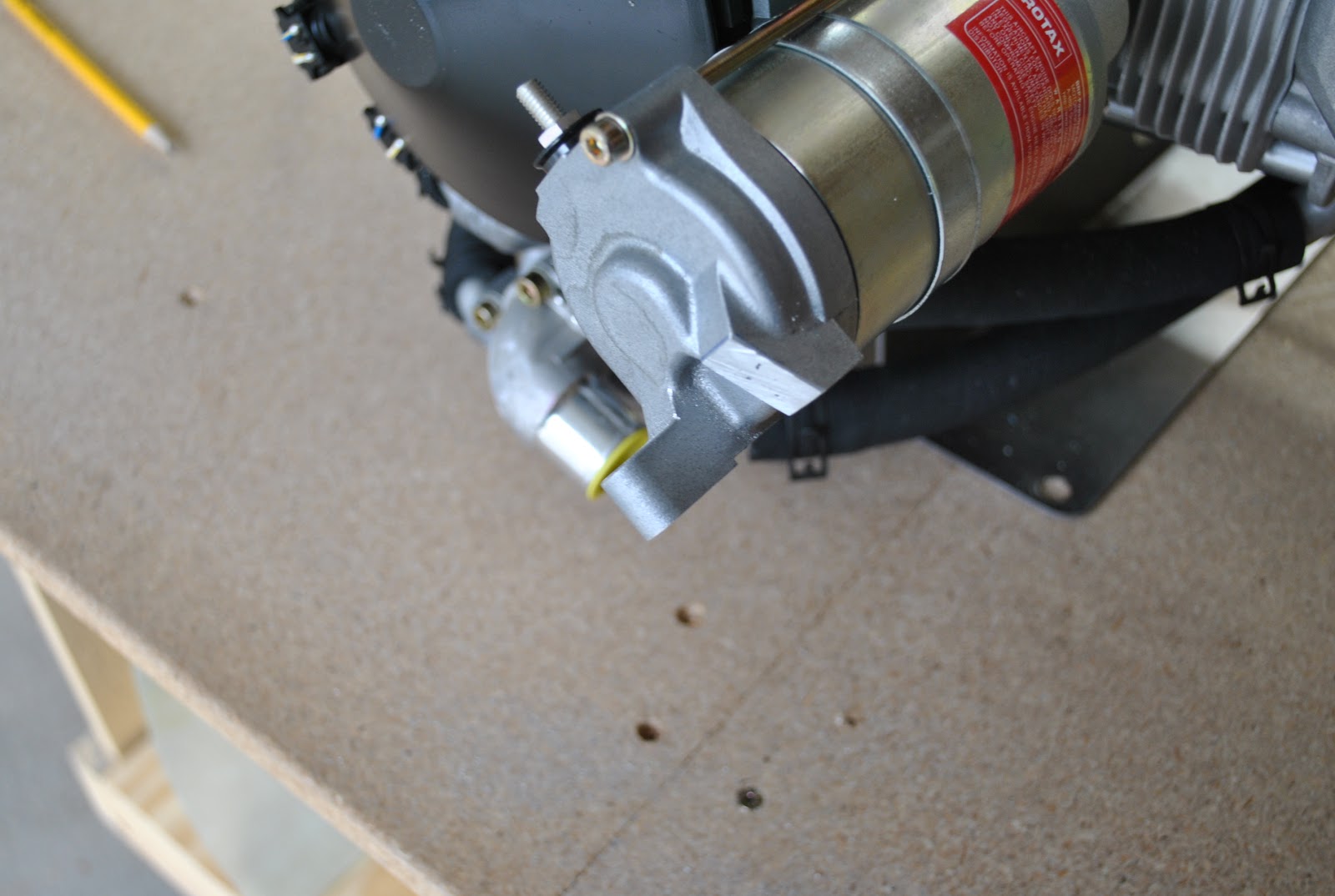
from the hoses I proceeded to install the engine mount.  I placed tape on the legs of the engine mount to avoid scratching the powder coat as instructed.  As I began installing the mount it became obvious that I was not going to be able to get it in place without removing the electronics module mounting bracket I was not able to remove earlier.  By holding the metal end of the rubber shock 
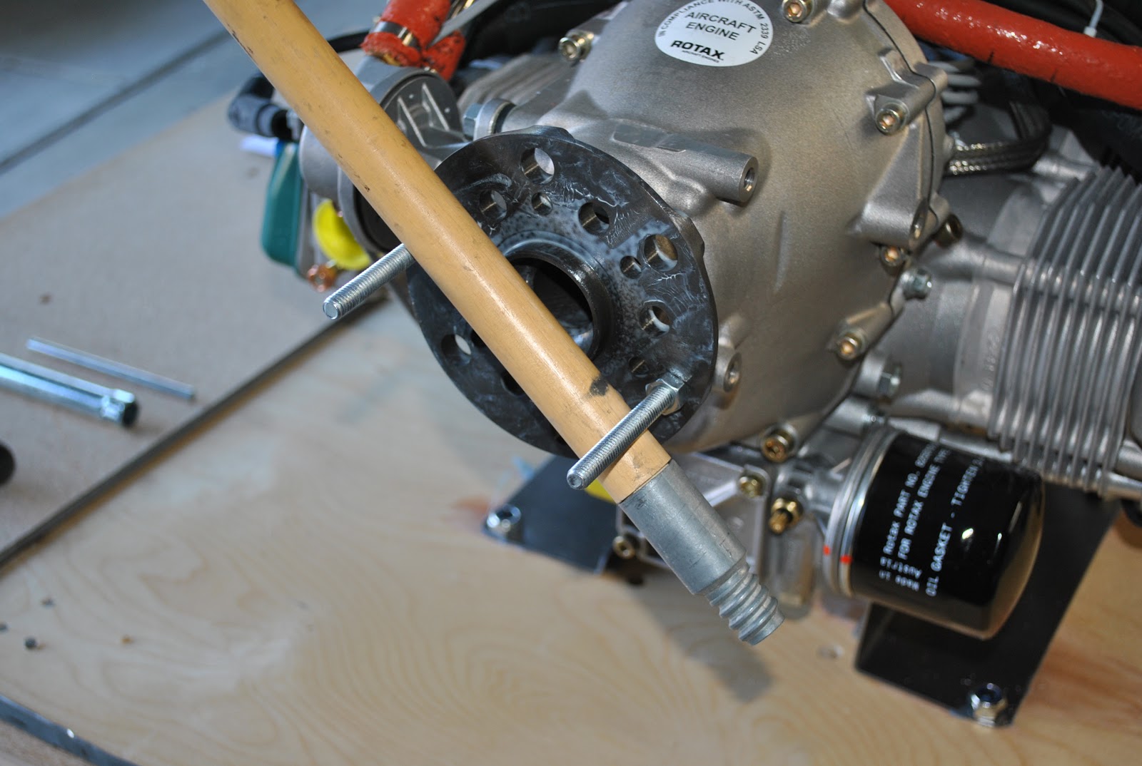
absorber I was able to remove the bracket and attach it to the module.  With the bracket out of the way I was able to rotate the engine mount ring into place and make the attachment to the engine.  I had to go on line to look up the Rotax Illustrated Parts Catalog so I could find the torque values for the bolts holding the engine mount in place.  The bolts are to be torque to 30 ft. lbs.  After the engine mount was installed I put the 2x4 block under the front of the engine and clamped the ring down to the table to give the engine some stability.

Wednesday, December 26, 2012

Paint Cooling Shroud

This evening I finished cleaning up the cooling shroud and applied a coat of gray primer.  High heat type.  After allowing it to dry I applied a coat of dark gray finish paint on the cooling shroud.  It will look good I hope.

Friday, December 21, 2012

Engine Cooling Shroud

This has been a very difficult month to say the least.  On December 4th our daughter, Kerri, had major oral surgery.  The procedures she underwent were performed by and ENT Dr. and an oral surgeon.    They fixed a deviated septum, performed a UPP (remove the uvula and remove a portion of the soft pallet, cut a small window in her chin and pulled her tongue forward 4 mm and cut and removed a wedge out of her tongue and stitched it back together.  She was in the Shock Trauma ICU for 10 days and in Adult ICU for 3-more days.  I spent every afternoon and evening visiting her.  She is now home and well on the road to recovery.  This afternoon I was able to work on the airplane again.
 It is pretty cold outside, but the sun was shining so I set up on the driveway.  Last week I received and inventoried the landing gear SB modification kit from Vans.  I will begin making the necessary mods soon. 
Today I worked on the engine cooling shroud.  I had marked the shroud previously so I started to remove the excess fiberglass to the scribe lines.  After removing the bulk of the material I slipped it in place on the engine.  I used my Dremel tool and a cutting disc to cut the fiberglass.  The fit was pretty good, but it could be better.  I used the Dremel tool with a small sanding drum to remove the fiberglass material to the scribe lines.  I put it back on the engine and the fit was considerably better, but not good enough.  I used a Sharpie to mark some places that needed additional work.  After cutting out some material to clear the cylinder fins on one end and removing a small section from the rear of the shroud it fits pretty good.

I also drilled a ¾" hole for the flexible tube that will provide cooling to the rectifier.  I also used a Sharpie and a pencil to mark the top of the engine for the RTV that will be used to install the shroud.

Wednesday, December 5, 2012

Starter Top Lug and Cooling Shroud

I started today by marking the top lug on the starter.  I used a hack saw to remove the lug and a file to smooth the cut surface and deburr the edges.  I also made a paper patter of the end cut out for the cooling shroud.  I used my bevel square to help me mark the end of the shroud 5/16" down the face.  I marked the end of the shroud accordingly.
After marking the end of the shroud I discovered there are scribe lines inside.  I will trim to the scribe lines and then cut the ends.

Monday, December 3, 2012

Intake Manifolds, Wiring and Fluid Tank and Hose Removal

Today I started taking components off of the top of the engine.  I removed the wiring harness clamps and reattached the harness with a new bolt and spacer.  
I removed the back cover over the fly wheel and checked the trip coils.  I removed 1-spark plug per cylinder and used a broom handle to turn the engine to check the coil spaces.   I determined they are fine from the factory. I re-installed the back cover. 
I removed the intake manifolds and taped the openings in the cylinders.  I also removed the wiring harness and ignition module.   It didn't come off like the drawings showed, but I was able to remove it.   I flipped the manifolds, hoses and wires up over the gear box.
After lifting manifolds and hoses I was able to remove the fluid tank and hoses.  I also marked and rotated the ignition module mounting bracket as instructed.

Friday, November 23, 2012

Photograph Engine and Start Removing Parts

This morning I removed the plastic from around the engine and took a dozen or more photographs for reference.  These are a few of them.
After photographing the engine from many different angles I removed, rotated and reinstalled the water inlet elbow on the lower front.  I also labeled the ignition harness electrical connections as shown on the drawings.
I need to find the torque values from the ROTAX manual and torque to bolts on the inlet fitting.  I also removed the  screw from the ignition harness clamp and pulled the harness away.  I also removed the connections from the bracket and pulled them apart.

Tuesday, November 20, 2012

Firewall Forward Wiring Continues

This afternoon I continued to install the firewall forward wiring.  I stripped the ends of the EGT exhaust  gas temp wiring harness freeing the yellow and red wires.  I stripped the wires and crimped on the male electrical c connectors included.  I also cut the connectors off of the ends of the EGT sensors and crimped new female connectors to those wires.
I installed the wires from the wiring harness into the manifold pressure sensor connector and installed the connector into the sensor mounted on the firewall.  The wires are really long so I coiled them and taped them together.  I also installed the power wiring to and between the master relay and the starter relay.  There are still a lot of wires that need to be connected.  I have coiled them and wire tied them to the engine mount.

Thursday, November 15, 2012

Firewall Forward Wiring

It was really cold today.  I opened the garage and moved the forward portion of the fuselage out onto the driveway.  The sun was shining, but the air was cold.  I wore  my shop coat which made the afternoon more tolerable.  I started by removing the canopy and rear window and turtle deck skins.
I also removed the upper fuselage skin and proceeded to work on the wiring.  I installed the WH-00063 Firewall Forward Wiring Harness 25-pin sub D connector to the control module.  I then routed the wires past the cushioned clamp next to the cooling fan and out the firewall grommet.  I could not get the harness into the cushioned clamp so I used a wire tie to connect it to the clamp. I also attached the WH-00062 power wiring harness to the rear of the Power and Switch module and routed the wires thru the fire grommet.  I wire tied the power wires to the bundle of wires going past the Com Supports  I put a clam shell on the EGT 25-pin sub D connector and attached it to the RV-12 EGT Exhaust Gas Temp Wiring Harness and routed the wires thru the wire tie holding the bundle to the cushioned clamp and out the firewall grommet.
It is really tight quarters in the instrument shelf area and I am having trouble routing these new harnesses thru the existing cushioned clamps and snap bushings.  I am holding the harnesses in place by wire tying them to other wires running in the same areas.
I cut a 4" length of PT ¼" ID tube and inserted one end of the ¼" heat resistant tubing for the pitot.  I cut the ¼" pitot tube from the fuselage and inserted the end into the splice tube.  I routed the pitot tube thru the grommet in the firewall.  I coiled it around the GPS antenna shelf.  I also routed the wires from the wiring harnesses
I separated the red, green and black twisted wires from the WH-00063 harness.  I cut them to length, stripped the ends and crimped them to the corresponding colored wires on the fuel pressure sensor.
I inserted the white wires and yellow wire with the spade connectors into the Connector Housing for the Rectifier Regulator.  They snapped into place and a gentle tug assured they were properly seated.  I plugged the connector into the rectifier.  That's all for today.