Thursday, May 31, 2012

Section 42C Continues

At work today I painted the mounting plates for the GPS and the ELT antenna.  I primed both plates and then painted the GPS mounting plate gray to match the other painted components mounted to the firewall.  I painted the ELT antenna mounting plate TAN to match the interior of the airplane.  This evening I mounted both plates.  I had to drill out 3-rivets installed in the back brace behind the co-pilot position to mount the ELT antenna plate.  I used my nutplate jig to drill #40 holes for the nutplates.  I also final drilled #19 the rivet holes.  I riveted the nutplates in place and installed the ELT antenna mounting plate.  I then attached the GPS antenna to it's mounting plate.  I had to remove some of the plate material at the edge of the large hole to allow the cable to pass through without being smashed.  I used my handheld nibblers to remove the same amount of material from the antenna shelf previously attached to the firewall.  The antenna attached to the mounting plate and the mounting plate attached to the antenna shelf like they were designed to do so.
I ran the GPS cable through the grommet in the firewall and through the snap bushings and
cushioned clamp on the instrument shelf.  I inserted the pins into the GPS D-sub connector and the installed the inserted the connector into the control module.
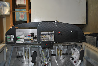
The plans indicate installing Switch module and the center instrument panel with flat head screws.  My plan is to install the panels with the black 632 pan head screws I ordered from Fastenal.  After reading some new information I learned that it would be a good idea to install the center panel section with flat head screws because the "THROTTLE", "CHOKE" an "CABIN HEAT" labels will cover the heads of the screws.  Pan head screws in that location will be a problem.  So I decided to counter sink the 6-each screw holes at the bottom of the center panel.  I was concerned that the cutter would rip the carbon fiber vinyl I have already installed on the instrument panels.  I set up the microstop in the drill press and proceeded to countersink the first hole.  I went perfectly.  I then countersunk the remaining 5-holes.  I painted the holes with a black marker so the aluminum won't show after the screw is installed.  I used some flat black paint to paint the heads of 6-flat head screws.  I will be ready to attach the center panel after I have repaired the switch module.  I am waiting for the parts Van's said they put in the mail yesterday.

Wednesday, May 30, 2012

Started Section 42C – Install Instrumentation

This evening I started working on section 42C.  The first thing I did was break off the stud on the upper left corner of the fuse/switch module.  I attempted to install the module and I think I cross threaded the fastener.  I didn't know my own strength because it just sheared off.  I sent a picture of what I had done to Van's.  They are sending me new studs for the corner.  I need to be more careful.
I installed the control module to the instrument shelf.  I also connected the 'fuselage', 'optional' and 'autopilot' connectors to the control module.
I attached the engine monitoring module to the fire wall and the back-up battery to the instrument shelf.  I installed the FFIS connector to the control module.   I routed the harness wires through the cushioned clamp and attached the USB connection to the instrument shelf and hooked up the battery connection.  I also installed the connectors to the engine monitoring module.  There are a lot of wires but the harnesses all seem to be well made and everything fits just as it should.  I hope it continues to go this way through the remainder of the build.  I also installed the Skyview screen and the ignition module to the instrument panel.  I hooked up the appropriate harness connections to both.  
I installed the fuses into the fuse/switch module.  I will need to replace the broken stud before I can install the module on the instrument panel.  I also installed the fuse label to the fuse holder.  I installed the extra fuses and attached the Velcro.  I installed the extra fuse holder to the inside of the map box door.
I installed the transponder to the firewall.  I also installed the transponder antenna  cable and harness to the transponder unit.  I ran the harness wires through the appropriate snap bushings, the cushioned clamp and attached the connector to the control module.  I routed the harness for the intercom from the control module to the intercom unit attached to the instrument panel.  I connected both ends to the appropriate fittings.   I attached the phone cable to the ELT remote switch previously attached to the instrument panel.  I crimped a ring terminal to the ELT switch ground wire and attached it to the fastener at the corner of the cooling fan.  I put 2-wire ties on the phone cord to furnish strain relief to the ground wires. 
I prepped the 2-mounting plates for paint.  One is for the GPS antenna and the other is for the ELT antenna.  I will paint them tomorrow.  I installed the fasteners to attach the map box to the instrument shelf one more time.  I hope this is the last time I have to do that.

Monday, May 28, 2012

Nearing Completion of Section 42D

Today is Memorial Day.  A day to give thanks for those who have defended our freedoms.  The flags are flying in the neighborhood today.  This morning, after pulling weeds in the flower beds and watering the vegetable garden I started to work on finishing up Section 42D.  I put the 9-pin D-sub connector on the 8-wires to the tailcone.  The 2-twisted pair and the 4-wire conductor.  I also put the ¼" nylon connectors on the static and pitot air lines.  These are now ready to be attached to the ADAHRS.  I left the wire ties loose until the ADAHRS is installed.  I will most likely pull the excess wires back and loop them near the last bulkhead as they enter the tailcone.  At that point I will tighten the wire ties.
I marked the AP disconnect wires and then cut them.  I installed Molex pins on the wires connected to the button and installed Molex receivers on the fuselage wires.  I inserted the Molex receivers into the appropriate half of the connector.  I will insert the pins in the other half of the connector after I install it in the center section of the instrument panel.
I rolled the fuselage back upright and worked on the headset power wires.  I pulled them through the last rib snap bushing on each side and then put a piece of heat shrink on the ends.  I wire tied them to the headset wires.  I then pulled the Nav power wires through the last snap bushing and attached them to the floating wing connectors.  That portion of Section 42D is finally finished.  While the fuselage was in the upright position I decided to install the upper engine mount to the firewall.  I drilled the holes to 3/8" and installed the engine mount with the appropriate nuts, bolts, washers and cotter pins.
I replaced the cover plates over the floating wing connectors and rolled the fuselage back on its side.  Next I cleaned up and put away all of the tools and materials I have had set up in the garage over the last several days.  I turned my attention to the instrument panels.  I used the microstop to countersink the center and left instrument panels.  I also prepped the Instrument panel support angle  and deburred the edges.  I then riveted the support angle to the left panel and riveted nutplates to the left and center panels.  Next I put the vinyl carbon fiber wrap on the center and left panels.
Of course I had already installed the vinyl wrap on the right panel a few weeks ago.  I did my best to line up the diagonal lines from panel to panel.  I think I did a pretty good job.  I have learned a lot about installing this stuff.  The heat gun really helps to get the stuff into the inside corners.  After installing the vinyl wrap on the center and left instrument panels I decided to attach the ELT remote switch and the intercom to the right panel.  I read though the instructions in both Section 42D and Section 42 to get it right.  I hooked the panels together for the full effect.  I think they look pretty good.
I took the panels down to the garage and clecoed them in place.  I like what I see.

Saturday, May 26, 2012

The Wiring Madness Continues

This is a recount of what has occurred over the last few of days.  After calming the tangle of wires on the instrument shelf it was time to start installing the conversion harnesses.  I set up my small tables in the garage to create a work bench and then jumped in.  I reinstalled the pitot air tube so I could wire tie the tunnel harness connector to it.  I attached the WH-00026 (Optional) and WH-00036 (Tunnel) conversion harnesses to the fuselage Tunnel and Optional harnesses.  I used the D-sub backshell interconnects with some blue Loctite in the process.

I then uncoiled the conversion harnesses.  There is a mess of wires that must be run down through the instrument shelf and to the center section of the airplane.  I loosened the over rudder wire keeper and started pushing the wires through.  With the help of some long forceps I was able to capture the taped ends of the wires and pull then down into the tunnel.  I am not sure how I was able to get the wires through the rat's nest of wires in the tunnel, but I was able to get them through.  By hook and by crook I was able to get all of the wires into the center section.
I then turned my attention to the dreaded page 42D-20 and the pilot/co-pilot headset harness conversion.  The instructions say to attach the existing RZ194 harness wires to the new RZ943 extension.  Likewise, attach the RZ195 existing harness to the new RZ942 extension wires.  That is all fine and good, but my existing wiring was labeled Pilot and Co-Pilot .  I was a bit unclear as to which of the existing harnesses was the RZ194 and which was the RZ195.  I looked through the old drawings and could find no reference to the RZ numbers.  I called Van's support and asked if they could identify them for me.  I was referred to the new electrical drawings issued on the website.  They helped me find the answer and pointed out that I should use the new drawings to help find the information I need.  I thanked the support guy for helping me identify the Pilot harness as RZ194 and the Co-Pilot as RZ195.  I proceeded to attach the appropriate wires of the existing harnesses to the correct wires of the new extensions.  I pulled this newly created harness through the snap bushings and cushioned clamp to the left side of the instrument shelf and proceeded to insert the pins into the D-sub connectors.  I wire tied the new wires to the appropriate S-sub wires.
Next I turned my attention to taming the wild array of wires in the forward tunnel.  After looping and wire tying and re-tying and removing ties as I worked I was able to make a huge mess into a much tamer and manageable run of wires.
Next I ran the wires ADAHRS wires back to the tailcone.  What a project!  I was able to tape the twisted pairs of wires to the sheathed wires and started to pull them through the wire looms and bulkheads.  There is not much room in the snap bushings and I really had to do some figuring to get them through.  At one point I thought I might need to drill some new hole and insert some additional snap bushings but there was no way to get a drill into the spaces to do so.  I inserted the 4 sheathed wires to the tailcone in a piece of ¼" tubing.  But cutting the end of the tube at an angle I was able to get it to go through the snap bushings.  I then used my wire spoon and was able to get the twisted pairs through the bushings.  What a tight fit that was.  After considerable pushing and pulling and pleading I was able to get the wires into the tailcone.
I inserted the white/red wire through the bushings using forceps and a lot of persuasion and got it to the ELT area and crimped on a butt splice.
Next I ran the orange/black headset and the white (should be yellow/red) Nav power wires for the wing lighting to each side of the fuselage.  I will wait until I roll the fuselage back upright to so I can remove the cover plates and make the attachments.  I also removed the WH-B148 wire from the power outlet and pulled it out of the tunnel.  I crimped a spade connector to the power outlet wire and attached it to the outlet.  The wiring is now tamed but it looks like I have been in surgery.

Tuesday, May 22, 2012

Continued Working on Section 42D

This evening I continued to work on making the changes called out in section 42D.  I attached the template to the forward left upper section of the firewall and drilled the 4-holes indicated.   Next I attached the template to the top of the tailcone and drilled the holes for the ADAHRS mounting brackets.
I prepped, primed, installed nutplates and then riveted in the instrument stack support angles and the com support angles to the instrument shelf.  I also drilled the F-1203A and F-1202F bulkheads and installed the snap bushings.  I also drilled and installed the snap bushing in the F-1207D-L bulkhead channel.  I bought a new angle drill because the only way I could drill the hole would be to remove the AP servo.  I was unwilling to do that so I now own an angle drill.
I then prepped and primed the ADAHRS  brackets before installing them in the tailcone.  After priming I clecoed them in place and then riveted them in.  
I then turned my attention to the existing D-sub connectors and the wiring on top of the instrument shelf.  I also decided to remove the AP-74 auto pilot D-sub connector and associated wiring.  I cut off the wires just after the heat shrink on the optional D-sub connector and put a small piece of heat shrink on each wire.  I then put heat shrink over the bundle.  Next I decided to install the AP disconnect switch I left out because I knew I would be changing the center panel with the Sky View update.  It was simple enough to install.  Next I pulled the wires to the Main and Optional D-subs through the snap bushings in the instrument shelf.  What a tangled mess of wires there is below the shelf now.   I will have to get them pulled into the tunnel and then form a large loop and wire tie them together.
I continued to clean-up the wires on the instrument shelf.  I put labels on the Tunnel and Optional D-sub connectors.  I also attached the Xpndr Ant cable extension.  I am ready to continue with the installation of the conversion harnesses.