I didn't take any pictures today, but I should
have. There are a couple of small
(1" or less) air bubbles that have developed in the brake lines. We got down the oil pump can and filled it
with brake fluid. I used a large syringe
to a piece of tubing and used this apparatus to draw the brake fluid from the
reservoir in the engine compartment. I
attached the tubing from the oil pump to the right brake caliper bleeder valve,
opened the valve and began pumping. I
was able to push the bubbles out of the right brake system. Everything seems to be fine on the right
side. I attached the tubing to the left
brake caliper and opened the bleeder valve.
I began pumping and the bubbles began to move and then disappeared. The bubbles in the left system moved to the
co-pilot left master cylinder and entered
the cylinder. We stopped and
waited. Slowly the bubble began to come
back out of the cylinder. We tried
again. The same thing happened. Frustrated we decided to call it a day.
Friday, January 31, 2014
Wednesday, January 29, 2014
Baggage Upholstery Panel and New Fuel Vent


Today I reworked the right strap I attached
to the baggage bulkhead panel for the installation of the bulkhead upholstery
panel. I removed the small section of
the panel that is behind the fuel tank.
The modification is to allow access to the tail cone without removing
the fuel tank which must be done to remove the full sized panel. Because I installed a screw to attach the
strap to the stationary part of the panel I would have to remove the tank to
remove the screw in the strap which defeats the purpose of the removable
section of the access panel. I connected
the panels together and drilled out the rivet attaching the strap to the
removable section of the access panel. I
installed a nutplate in the access panel so that screw can be removed and the
removable part of the panel can be taken out.
I reinstalled the whole panel and then put the upholstered panel in
place. I was able to attach it with the
fasteners provided.
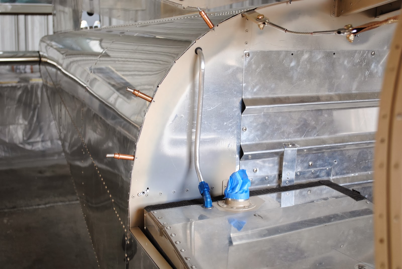
I drilled a hole in the upholstered panel for the new fuel tank
vent line. I also drilled a hole through
the bulkhead and installed a snap bushing.
I put the tank back into the airplane and then proceeded to make the
tubing section which goes from the tank fitting through the bulkhead. It took 3-times to make a tube that fits correctly. The first tube I made according to the
drawings and it was too short to reach the fitting on the fuel tank. I made another tube and after I clamped it
into the flaring tool I dropped the tool and badly kinked the tube. The third attempt was a success. I have a piece of tubing bent to the correct
configuration with a flared fitting on the right end. The other end passes through the
bulkhead. I will need to slot the
upholstered panel so I can slide it into place because once the tubing is
installed it cannot be removed from passing through the bulkhead. Now I need to make the tubing pieces which
are installed behind the bulkhead to vent the tank through the bottom of the
fuselage.
Monday, January 27, 2014
Baggage Bulkhead Upholstery


Today I spent a few hours working on the
baggage bulkhead upholstery attachment.
I decided to put four of the five screws to attach the upholstery panel
to the bulkhead along the bottom part of the panel.
Because the panel attaches to the flat of the bulkhead and also the
corrugated access panel to the tailcone area I decided to put in some attachment
straps. The straps go between 2-of the corrugations
in 2-places. First I attached the tailcone
access panel to the rear bulkhead. I cut
some straps out of some scrap material and bent them to fit the angle of the
corrugations. I drilled and clecoed the
strap to the left side of the access panel.
I then began working on the strap for the right
side of the panel. I cut and bent the
strap to fit the panel. I drilled,
clecoed and then riveted the right strap in place. After riveting the right strap I realized the
strap was riveted to the both stationary and permanent parts of the panel. I
will not be able to remove the panel if the strap is riveted to the permanent
portion the remains in place.
Accordingly I drilled out the rivet and installed a nutplate so the
strap can be removed with the access panel.
I had previously drilled the upholstered panel for the 5-attachment
screws and had transferred the location of the holes onto the straps and the surrounding
bulkhead.

I then proceeded to install nutplates on the straps. After attaching the nutplates to the straps I
drilled and installed nutplates on the flat bulkhead panels. Because holding the upholstered panel to the
bulkhead is not a structural challenge I opted to use an unorthodox method of
installing the nutplates. I drilled a ¼"
hole for the center of each nutplate. I
also drilled the holes in the ears of the nutplates to #30.


Tomorrow will be a new day and I will once
again work on the bulkhead, the upholstery panel and see if I can finally get
it right. I am also working on a method
of reinforcing the panel to make the parts lineup correctly and present a flat
panel. Right now the panel sort of bends
in when it is screwed in place.
Friday, January 24, 2014
Fuel Tank Vent

Today I did some work towards the installation
of the new fuel tank vent system. I
removed the right turtle deck. I also
checked on the Pro-Seal installed a couple of days ago. It seems to be curing just fine. All of the rivets have been set. When I install the sender plate on the
forward end of the tank I will make sure all of the rivet heads have been
filled with Pro-Seal. I did a test fit
of the baggage area upholstery. The
vinyl covered part the installs above the fuel tank. I marked the location for the ½" diameter
hole that will be drilled through the upholstered bulkhead cover and the bulkhead.


I then decided to cash-it-in for the day.

I covered the cockpit area with some plastic
sheeting to keep the drips out.
Wednesday, January 22, 2014
Fuel Tank Modifications Continue


Today Tim went with me to the hangar. We worked on the fuel tank together. We mixed up a batch of Pro-Seal and started
installing some of the modification parts and pieces. First we installed the new vent fitting at
the rear of the tank. It was a challenge to get the fitting into the hole along
with Pro-seal and then get a retaining nut to tighten. I was able to get it on and it looks good
from the top and from the inside.


Next we tackled the installation of the
reinforcement plates in the forward corners.
I clecoed the plates in place and then we began to install the Cherry
Max rivets in the right front corner. What
a mess it made. We then installed the
plate in the left front corner. We
installed the Cherry Max rivets and then the 3-machine screws and nuts. We also replaced all of the blind rivets
along the bottom and edges of the tank.

All of the rivets and fasteners are installed
with Pro-Seal. The last thing we did was
install the Moller fuel gauge in the top of the tank. I will let it cure for a couple of days
before I do a final inside cleaning and install the sender plate on the forward
end. After I install the sender plate and let the Pro-Seal
cure for a few days I will retest for leaks.
My next efforts will be to fabricate and install the vent plumbing system
and the upholstery on the baggage compartment bulkhead.
Tuesday, January 21, 2014
Fuel Tank Mod Continue


Today I continued to work on the fuel
tank. I brought a ½" chisel from my
shop to help remove the Pro-Seal from the forward corners inside of the fuel
tank. It worked rather well. With the excess Pro-Seal removed I was able
to cleco the reinforcement plates to the tank corners. I clecoed the right corner plate to the tank
and drilled the required #30 holes. I
then moved the plate to the inside of the tank and final drilled the #19
holes. Because the mandrel was still
inside one of the rivets one of the holes is elongated. I will need to fill the hole with plenty of Pro-Seal
when I set the rivets. I then clecoed
the left corner plate in place inside of the tank. I am now ready to rivet these plates in place
and install new rivets in the additional drilled out locations.


I used a ScotchBrite wheel on my angle
grinder to buff the forward end of the tank and the sender plate so they are
ready to be Pro-Sealed in place. I
should have the tank reassembled in the next few days.
Monday, January 20, 2014
Fuel Tank, Stabilator Tips and Stuff


Today I worked on several things. I took the fuel tank back out to the
hangar. I also did a couple of other
things. I discovered that the switch I
was able to get from OTTO is not going to work.
It needs a power source to illuminate the green light on the
switch. I suppose I could get someone to
help me tap into a power source but instead I went to Standard Electronics
Supply and purchased an ON/OFF rocker switch.
I installed it in the fuel pump power line and it works just great. I will mount it in the instrument panel below
the ELT switch after I have my DAR inspection and certification. For now it is installed in the line and is
under the map box so the system works like it is supposed to. To turn off the electric fuel pump you must
pull the fuse. That is per Van's
design. So, if you need to power up the
electrical system, in order to not run the electric fuel pump you must pull the
fuse. After the inspection I will be
able to turn the pump on or off from the instrument panel. I also framed the airshow poster I took down
the other day to install the white board.
I had a gold colored frame I had purchased years ago. I went to Rueles and purchased a piece of
glass a some red matt board. While at
the hangar I put it together. I need
some picture hanging wire and I will be able to hang it in the hangar. Maybe I can do so tomorrow.


After that I tackled the fuel tank. I used my holesaw to make a hole for the
Moller fuel gauge. After cutting the
hole I used the reinforcing ring to layout the screw holes. I drilled and then deburred all of the
holes. I also drilled a hole for the new
fuel tank vent.


I
used my shop vac top clean the debris from inside and outside the tank. I then began drilling out the rivets in
preparation for installing the forward lower corner tank reinforcement plates
called out in the fuel tank service notice. It is a real challenge to get the rivets
drilled our correctly. If the mandrel is
still in the rivet it doesn't drill very well.
These are solid back blind rivets so the mandrels can't be punched out
very easily. So far I have been able to
get them out. Now the challenge is
removing the Pre-Seal from the inside corners of the tank. I really gooped them up when I built the tank. Now I am paying the price for doings such a
good job.


I turned my
attention to the stabilator tips. I
finalized the layout and drilling of the left tip. I bent the tabs on the right tip bracket and
attached it to the stabilator. I then
test fit the right tip. It fits pretty
well.


I went through the same layout procedure on the
right tip because it seemed to work so well on the left tip. I put tape around the stabilator and marked
the centerline of the holes in the tabs onto the tape. I then put tape around the tip and slid it
onto the bracket. I transferred the
marks from the stabilator to the tip. I
then determined the location of the holes and marked them on the layout
lines. I drilled the holes in the tip
and installed it on the bracket with clecoes.
I am impressed with how well the tips fit on both sides. I am planning to have the tips painted with the
Maroon color. I will also have the wing
tips painted Maroon so they wings and stabilator are similar. That is all for today. I will be back tomorrow.
Friday, January 17, 2014
Tank Modification and Stabilator Tips


While at the hangar I decided to add some
additional clecoes to the right side of the rear window at the turtle
deck. By adding some additional clecoes
the turtle deck and window appear to fit together better.


I then began to turn my attention to the
stabilator tips. I ordered the tips kit over
a year ago. I have decided to prepare them
for mounting so I can have them painted when the airplane is painted later this
spring. The tips are ABS and are
attached to the ends of the stabilator with aluminum mounting plates. I bent the tabs on the mounting plate and
then attached the right mounting plate to the stabilator tip by inserting, but
not pulling 2-of the large blind rivets that came with the kit. I will
have to drill additional holes for 2-of the rivets. I wrapped blued tape along the edge of the
stabilator to mark the location of the attachment holes in the tabs. I test fit the tip. It looks like it is going to fit just right.


I wrapped tape around the tip and transferred
the locations of the holes to the tape on the tip. I also marked the center of each hole on the
tip and drilled one hole to see if it lines up with the hole in the mounting
tab. It lined up just right. I marked the right tip with a piece of tape
inside that says "RIGHT". I
will need to put the same mark on the mounting plate.


Before going to the hangar today I spread a
thin layer of PolyGon on the fuel tank sender plate and the forward face of the
fuel tank. Upon returning home I cleaned
the Pro-Seal residue from the tank and the plate. It all come off and left the parts
clean. I will work on them with a
ScotchBrite pad before any reassembly takes place.
Subscribe to:
Posts (Atom)
