Friday, October 29, 2010

System Block Studs and Nuts

 
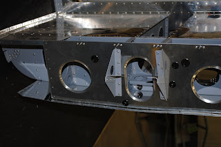
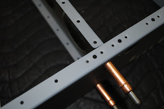
By using a small pair of vice-grips and my variable speed DeWalt drill with a Phillips bit I was able to tighten the lock nuts on the machine screws.  That section of the fuselage build in now complete.  
I am posting some additional pictures of the completed work.

Thursday, October 28, 2010

Install Rear Baggage Bulkhead & Servo Brackets


Today I finished riveting the left step floor in place.  I then prepped the rear baggage bulkhead for installation.  I deburred the edges and the lightening holes and dimpled the upper edge for the nutplates.  I then dimpled the nutplates and riveted them in place.
 
 
I separated the auto pilot servo brackets and along with the facet pump mounting bracket prepped the parts for priming.  I then primed them.
I  riveted the rear bulkhead and servo brackets in place and installed the snap bushings.
I clecoed the facet pump bracket in place and final drilled the 4-corner holes.  I then prepped and riveted the nutplates to the inside of the bracket and then riveted it in place on the bottom skin of the fuselage.
I inserted the machine screws through the bottom skin for the system blocks and started the nuts onto the bolts.  I will need some assistance in tightening the lock nuts all of the way onto the screws.

Wednesday, October 27, 2010

Installation of Step Floors

Today I dimpled a whole pile of nutplates.  I riveted 4-nutplates to the top flange of the step floor bulkhead.  I dimpled the #30 and #40 holes at the inboard edges of the step floors.  I installed 8-each nutplates as instructed.  I then began to rivet the step floors in place using the flush and pulled rivets.  I also installed the corner nutplates at the front corner edge of the floors where they meet the inboard ribs.  What a trick that was to get the nutplates oriented in the blind space they are located in.
I riveted the right step floor in place.  I will finish riveting the left floor tomorrow.

Thursday, October 21, 2010

Step Support Angles and Nutplates

This morning I separated the step support angles and nutplate brackets.  I cut the angles to length by separating them at the indicated hole.  I cut 2-angles down to 1" in width.  I also used the micro countersink to prep the brackets for the installation of the nutplates.  I then deburred the edges and installed the nutplates.  I clecoed the seat support angles to the seat ribs and match drilled the #30  holes in seat rib bulkhead to the seat support angle 
After match drilling the #30 holes into the support angles I final drilled the ¼" hole in the outboard bottom support angle and temporarily attached the steps.  I then matched drilled the ¼" hole at the top of the step attachment point.
I removed the steps from the bulkhead and removed the bulkhead from the ribs.  With the support angles attached I inserted a bolt in the nutplate bracket and then clamped the bracket to the support angle attached to the bulkhead.  I match drilled the holes in all 4- brackets.   
I then primed the support angles and the nutplate brackets.
I riveted the support angles and nutplate brackets and bulkhead to the ribs.  I set the step floors in place for reference.

Wednesday, October 20, 2010

Rivet Bottom Skins and Doublers

 Yesterday I emailed Van's Aircraft to ask a question about a note in the drawings.  It said I have the option to install 4-nutplates at some holes in the bottom skin.  The location is where a comm antenna will be installed.  The response from Van's is that unless I am a double-jointed concert pianist I should install the nutplates.  I had already decided to do so.  I needed to remove the bottom skin from the fuselage.  This morning I put lines through the holes defining a square on the bottom skin.  I used some 8-32 screws to hold the nutplates in place.  I then drilled one of the ear holes and then installed a cleco to hole the nutplates while I drilled the second holes.
I used the pop rivet dimple tool to dimple the nutplate fastener holes.  It worked really well.   I then installed CCR-264SS flush pulled rivets to hold the nutplates in place.  It went very well and the nutplates are now securely attached to the bottom skin.  It will make installing the antenna much easier.
 
After installing the nutplates I reattached the bottom skin to the fuselage and began inserting clecoes.  I clecoed the support angles by reaching through the channel opening.  I then clecoed the doubler plates to the bottom of the skin.  I finished installing the clecoes and then started at the bottom to pull rivets.
 
At this point the rivets are going in with little trouble.  
I continued to install rivets until the bottom skin was completed.
I turned the fuselage right side up and discovered I had not installed 8-rivets connecting the flaperon mixer bracket to the seat rib.  Luckily, with a lot of effort and the hand rivet puller with the rotating head I was able put all 8-rivets into the holes and pull them.  I was amazed that I was able to get the rivets to go in and that I didn't have to ream the holes.

Tuesday, October 19, 2010

Installed Fuselage Corner Skins and Bottom Skin

This morning I started turning the fuselage upside down.  After doing so I inserted the snap bushings into the various holes in the various bulkheads.  I then clecoed the corner skins onto the bottom of the fuselage.
After clecoing the corner skins in place I riveted them together and riveted them to the appropriate bulkhead.
I began to prep the fuselage bottom skin for installation.  I placed it on a work bench and dimpled the nutplate attachment holes at each of the access openings.  I also deburred the edges of the skin and the edges of the access openings.  
I used the Cleaveland edge tool to break the long side edges of the bottom skin.
After deburring and breaking the edges I riveted the nutplates in place and began  to cleco the bottom skin to the fuselage.

Monday, October 18, 2010

Bolt Control Column to Brackets

It was a major challenge, but I was able to install the washers between the brackets and fins and insert the bolts through the control column and the bearings.  I used a short piece of 3/16" dowel partially pointed as a space holder for the bolt.  I used blue masking tape to hold the washers together while I inserted them into the spaces.  By wrapping the tape around the edge of the washer stack and then using small scissors to trim the tape so it was only around the edges of the washers I was able to slip them between the bearings and the fins and then insert the sharpened dowel.  After the washers were engaged on the dowel I pulled the tape and it came cleanly off of the washers.  After the washers were in place I inserted the bolt, pushing the dowel out and then put on the washer and nut.  It was not as difficult an operation as I thought it would be.
After installing the control column I dimpled the step ribs and step bulkhead as called out in the drawings.  Next I riveted the step ribs to the seat bulkhead.  I then clecoed the step bulkhead to the step ribs.