This evening I
decided to install the POH Tray under the right side of the instrument
panel. It mounts below the Map Box in
the right panel. To do so I decided to
roll the fuselage over on its side one more time. I rolled up a couple of moving pads and
placed them under the tail cone. This
will cause the tail cone to be elevated and will support the aft portion of the
fuselage at the midsection so the flaperon torque arm and the clecoes holding
the top skins together clear the surface of the work table. I put the moving pads in place and shifted
the fuselage to the edge of the work table.
I then pulled the fuselage over and repositioned it on its side. The moving pads support the tail cone and the
fuselage rests on the forward midsection.
I moved the whole thing into the middle of the work table. I now have access to the interior of the fuselage
and under the instrument panel. I have a
lot of work to do inside and this will certainly make my job a lot easier. I need to cut and replace the wire ties
holding the tubing for the static air ports and the pitot air and wire harness
to the fuselage frame. I will have to
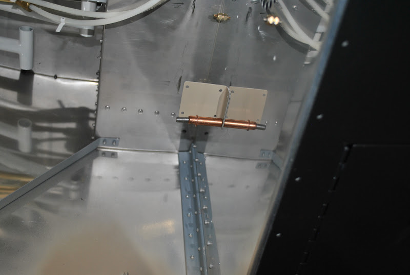
change the tubing in this area to accommodate the Skyview ADAHRS. I also want to install some tubing for the
AOA. This tubing will follow the current
pitot tube route from the ADAHRS location through the center of the fuselage
and out into the left wing. I might as
well get started on these changes while the fuselage is on its side.


As I began the installation
I was surprised to find the instrument shelf pre-drilled for the POH tray. I suppose that shouldn't have surprised me
because the POH Tray is used to replace the Map Box if the second Dynon display
screen is installed. I clecoed and
riveted the angle and POH Tray as shown.


I then mounted the
cover plates on the floor step and the tunnel.
I mounted the Map Holder on the tunnel and match drilled the holes in
the step cover. I removed the Map Holder
and installed the map support angle (Pocket Base). I match drilled the hole for the map support
angle in the step cover.

I removed the map support
angle, the floor step cover and the tunnel cover. I went into the shop and proceeded to prep
the floor step cover for the installation of the nutplates that will be used to
hold the map support angle and the Map Holder in place. I final drilled the holes in the floor step
cover. I used a screw to hold the
nutplates in place and then match drilled the #40 holes for the flush
rivets. After attaching the nutplates, clecoing
and drilling I had all of the nutplates located and the rivet holes
drilled. I used the rivet squeezer to
dimple the #40 holes for the flush rivets.
I also dimpled the holes in the ears of the nutplates. The next step was to rivet the nutplates in
place under the floor step cover. I completed
that step without any problems. I will
continue to work on the fuselage interior over the next several days.

Also, I read in
the RV-12 forum that someone who just recently ordered the Avionics kit was
told that it would be about 3-months before the kit is shipped. I decided to try and get a jump on things so
this afternoon I ordered the Skyview Avionics Kit. We'll see what Vans says about delivery.
