Thursday, September 15, 2011

Canopy and Roll Servo Installation

 
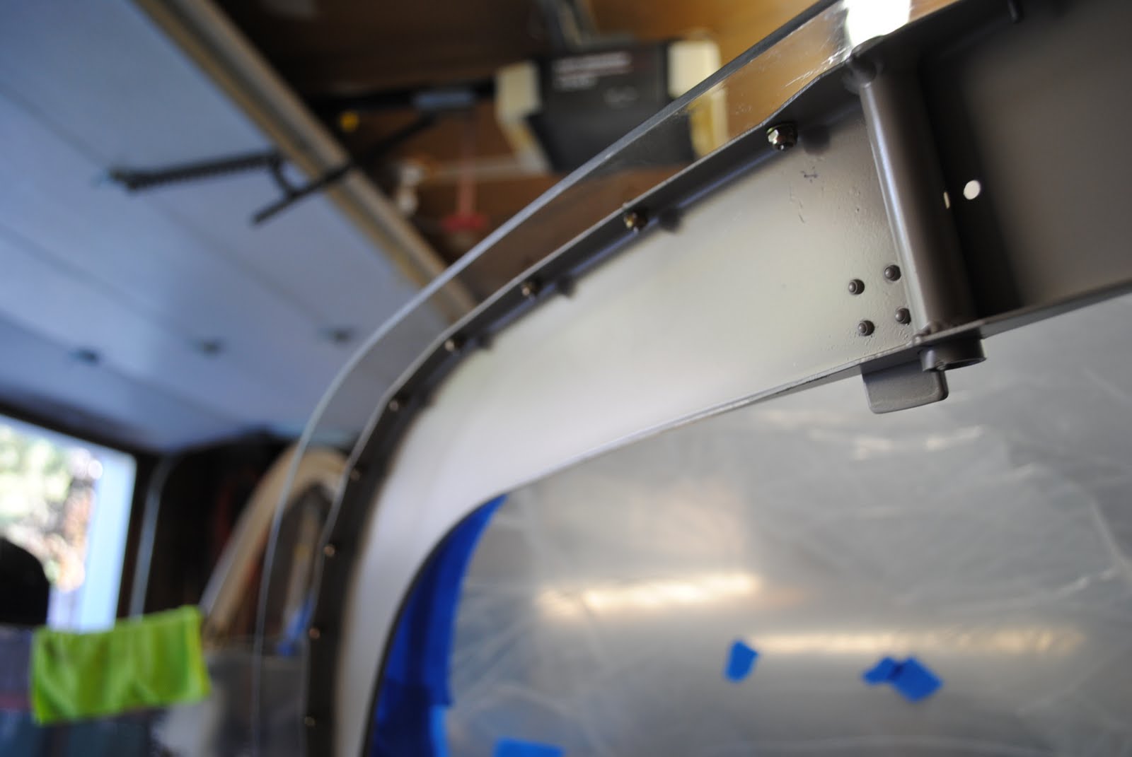
This evening I started by trimming the canopy guide blocks to clear the nuts on the inside of the canopy at the end of the canopy skit.  I used my Dremel tool with a course sanding drum to remove the corners of the guide blocks.  The problem was in trying to lift he canopy from one side, the nut caught on the guide block on the opposite side and the canopy would not lift up.  With the corners trimmed the canopy now opens and closes without any interference.
I also completed the installation of the canopy latch.  I had to squeeze the latch tube because the latch handle kept turning when the canopy was lowered and would lock the canopy closed.  The latch and latch blocks have all been installed.  

 
After working on the canopy latch and the canopy guide blocks I turned my attention to the installation of the roll servo.  The servos are difficult to reach.  The pitch servo is located under the pilot seat and below the roll servo is located below the floor level in the tail cone.  Both locations are difficult to reach when standing on the floor.  The roll servo located in the tailcone is almost impossible to get to.  To make things a bit easier I decided to roll the fuselage onto its side once more. I set up the saw horses next to the work table and put moving pads over them.  I placed a short table next to the canopy area and proceeded to install the servo and pushrod. 
 
I bolted the pushrod to the servo arm and bolted the servo in place on the brackets behind the baggage floor.  Next I had to unbolt the flaperon pushrods and reinstall the right bolt with the head on the inside of the connection.  I had to use a longer bolt to reassemble the left pushrod and attach the servo pushrod to the flaperon actuator.  I was able to get all of the bolts and appropriate washers installed and the nuts tightened.  Now to move on to the wiring connections.

 
I put the spade connectors together and indicated in the previous instructions, leaving the wires unconnected as instructed by Vans.  Then I tie wired the connections to the servo body.

Wednesday, September 14, 2011

Canopy and Pitch Servo

 
I used a blue marker to re-mark the cut line on the front of the Plexiglas canopy bubble.  I did not cut off this section of canopy when I was trimming the Plexiglas and now it will not clear the upper fuselage skin when tilting the canopy up.  After marking the Plexiglas I removed the canopy and placed it on the work table.  I used my Dremel tool with a cut off blade to cut off the 1/8" edge.  I used a sanding block with different roughness of sandpaper to finish the cut edge.
After cutting off the edge I cleaned up the mess and was ready to install the canopy back onto the fuselage.  I needed some help so I decided to wait until Arlene came home to give me a hand.  While waiting I wire tied the spade connectors for the pitch servo to the servo body as called for in the drawings.  It was not easy.  I also wire tied the noise filter to the connection bundle so it would not flop around in the compartment.  I asked Vans about the wires "not to be connected" if using a Dynon DEK 180 instrument package.  I was told they don't know if the Dynon Skyview will be the same but was told to leave the wires "not connected, but accessible."  They are.
 
Also while waiting I installed the gas struts for the canopy.  That later turned out to be a mistake because I could not get to the head of the screw with a screwdriver.  Oh well, live and learn.   
 
I also installed the canopy guide blocks on the roll bar.  They were pretty simple to install.  One on eachside of the roll bar.  I used some Loctite to lock the threads in the thin aluminum of the roll bar.
After Arlene got home I had her help me lift the canopy in place.  She helped me get the holes lined up so I could insert the bolts and washers into the pivot points.  That is when I discovered I was not able to tighten the screws and nuts for the gas strut connection to the canopy frame.  I had to remove the pivot bolt one at a time in order to lift the frame far enough to engage a screwdriver into the head of the screws.  I was finally able to get the gas struts attached and closed the canopy.  
 
It fit and then I learned that the nut on the last screw attaching the canopy skirt on each side interferes with the canopy guide blocks.  The drawings seem to indicate this is a possibility.  I will need to remove a corner of the guide blocks to allow the nut to pass without interference.  I have also decided I need to paint the inside of the forward arms on the canopy frame hammertone black because you can see these from inside of the cockpit with the canopy down in place.

Tuesday, September 13, 2011

Canopy and A/P Pitch Servo

 
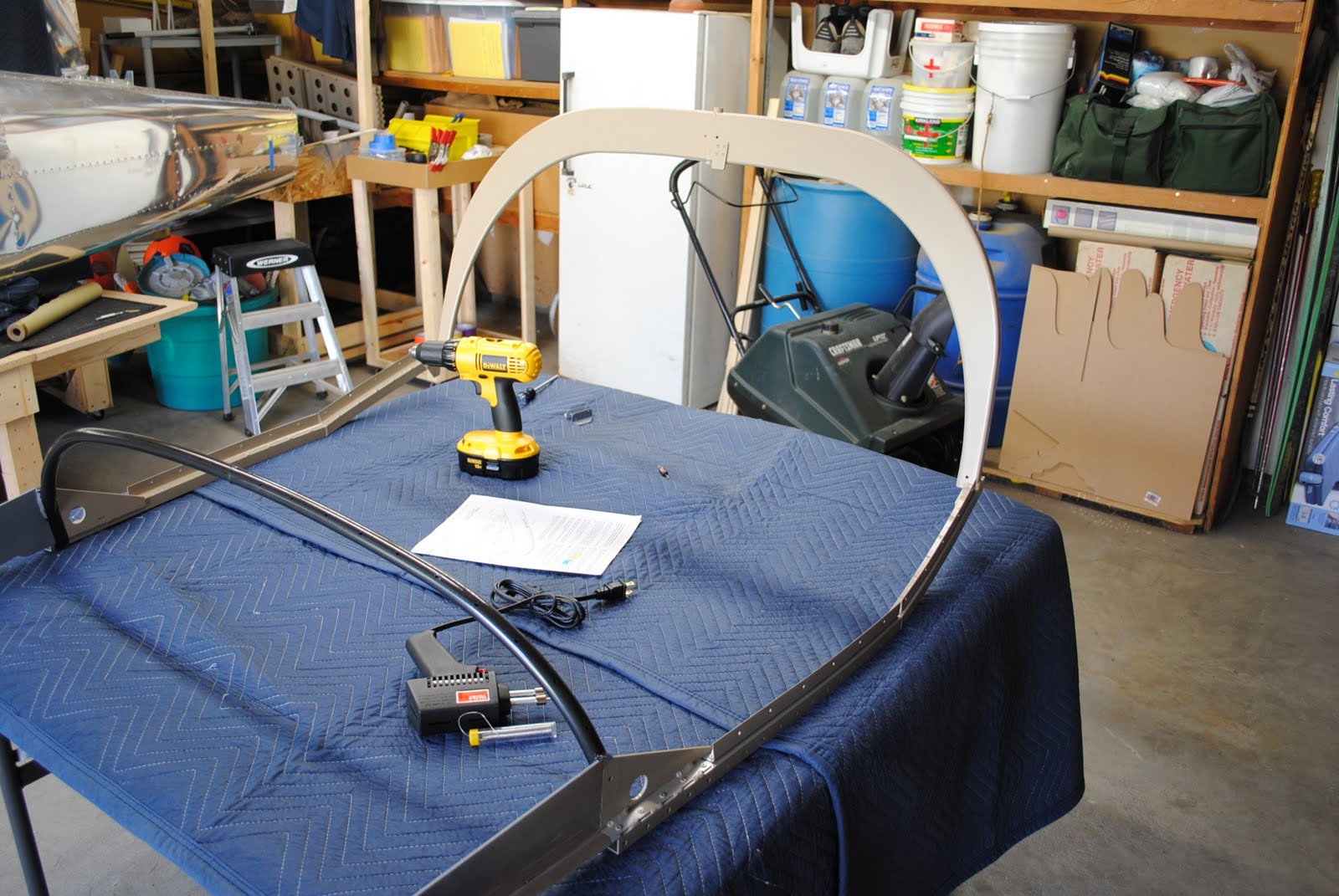
This evening I was able to do several things.  I started by stripping the masking paper and tape from the fuselage and canopy frame.  I set up the work tables and put the canopy frame on the table.  I also decided to solder the cockpit light to the power supply wires.  I put a small piece of heat shrink on the wires and then soldered them together.  I should be able to tuck the wires up behind the light and use some RTV sealant to hold them in place. 
I also installed the latch block to the bottom of the rear roll bar.  I used an 8-32 tap to cut threads into the holes in the bottom of the roll bar and then attached the block with 8-32 flat head screws.  I countersunk the screw holes before installing the block. 
 
 
Next I put the Plexiglas bubble on the canopy frame.  I installed clecoes in the front bow and rear roll bar.  Using the correct screws, washers and nuts I attached the canopy bubble to the rear roll bar.
 
Next I clecoed and then riveted the side skirts to the canopy frame.  After riveting the skirts and lift handles I used the screws, washers and nuts to attach the canopy bubble.
The next step was to rivet the canopy bubble to the front bow.  I used the hand rivet tool so I would not overstress or over-pull the rivets through the Plexiglas.  
 
I also installed the latch handle.  I had to file the top of the tube to get the handle to fit properly.  I put a light coat of grease on the latch handle tube and put some silicone 'aquarium sealant' around the hole in the top of the Plexiglas bubble at the latch handle tube.  Hopefully the latch will be water tight.
 
After working on the canopy I decided to start installing the Auto Pilot servos.  I set up the steel saw horses and put moving pads on them.  I then turned the fuselage on its side on the saw horses.
 
 
With the fuselage on its side I can more easily reach the areas where the servos are installed.  First I removed the nut and washer from the fastener installed in the seat rib where the pitch servo will beinstalled.  I set the servo in place and proceeded to install the screw and bolts that hold it in place.  After bolting the servo in place I installed the pitch pushrod.  One end attaches to the servo arm and the other end attaches to a bracket on the control column.  I connected the spade connectors from the fuselage to the corresponding connectors from the servo.  I also installed the noise filter that came with the servo kit.  There is a note in the drawings which says to leave some of the wires disconnected if installing the Dynon DEK 180.  I am going to contact Vans to see if that note also applies if you are installing the Dynon Dkyview.
 
 
After rolling the fuselage back upright I had my neighbor, Dave Gagon help me put the canopy on the fuselage.  I inserted the pivot bolts and tried to lift the canopy.  To my surprise, it will not open.  Earlier this evening I noticed some blue lines I had drawn on the front of the canopy bubble.  Apparently I had marked the front of the bubble so I could remove some of the Plexiglas so it would clear the instrument panel.  I used MEK to wipe the blue lines off of the Plexiglas.  I now understand that I should have removed about 1/8" from the front of the canopy bubble.  I will need to take the canopy off of the fuselage and make that adjustment.