Monday, March 18, 2013

Torqued Engine Mounting Bolts and Worked on Rectifier

 Today I went to Harbor Freight today and purchased some Crow's foot wrenches.  I was unable to torque the upper engine mount bolts because I was not able to get my  torque wrench in the space to make it work.   I used the formula to calculate the torque settings and proceeded to torque the upper bolts.  
When Arlene got home from work I had her sit in the cockpit.  Using a ratchet with an extension she was able to hold the heads of the lower bolts so I could torque them. 
After torquing the bolts I inserted the cotter pins and bent them into place.
I then began working the installation of the cooling shroud on the rectifier.  I deburred the edges of the shroud after removing the blue vinyl film.  I filled the corners and seams with gray RTV and allowed it to cure.  I removed the rectifier from the engine shelf and match drilled the fins to the holes in the shroud.
I riveted the shroud onto the rectifier and reinstalled the rectifier onto the engine shelf.  In the process of removing the rectifier I had to remove the fuel pressure sensor from the firewall.  I replaced it after reinstalling the rectifier.

Friday, March 15, 2013

Hang Engine on Air Frame

Today was a good day and a bad day.  I twisted the Banjo Bolt in two, but I also installed the engine.
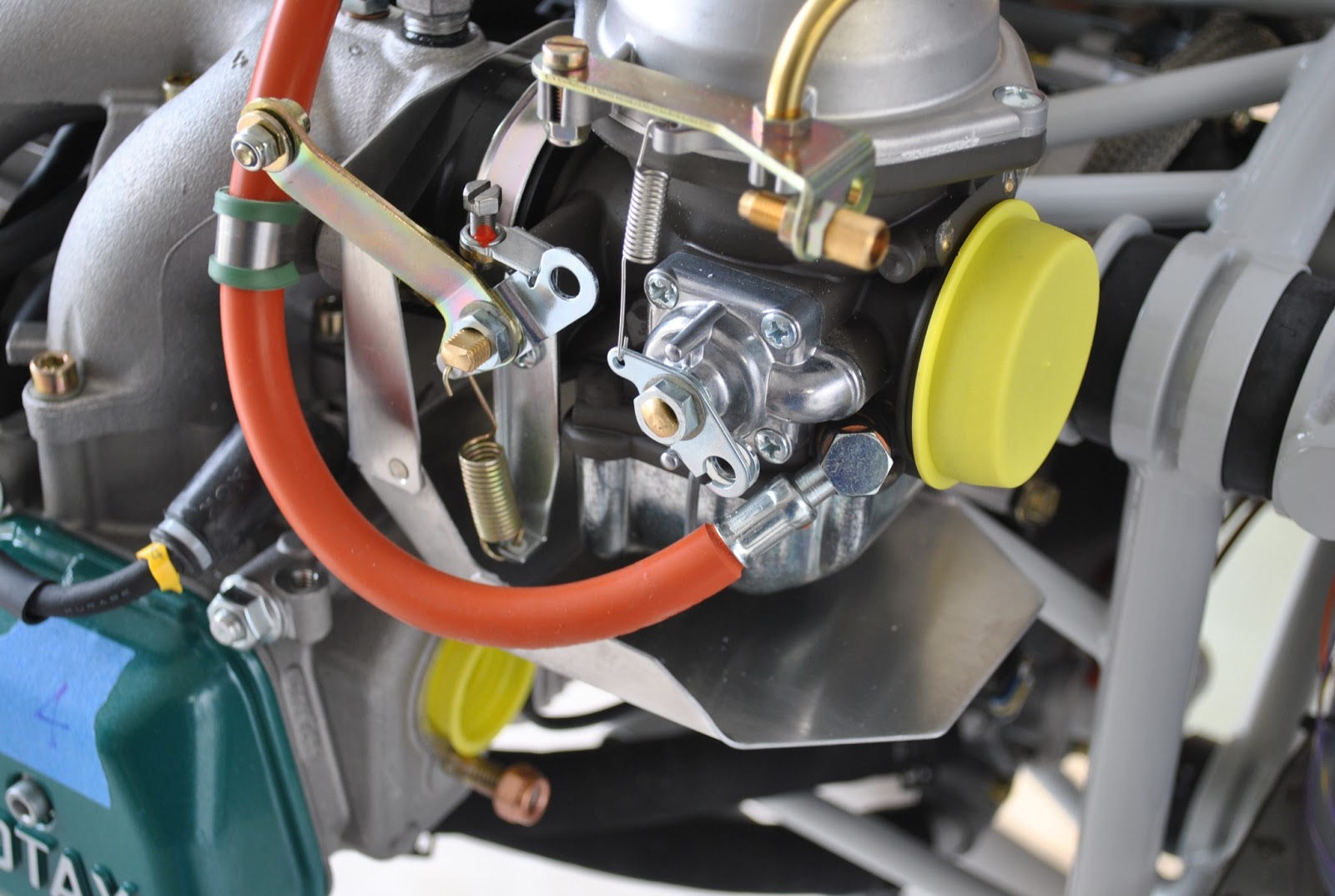
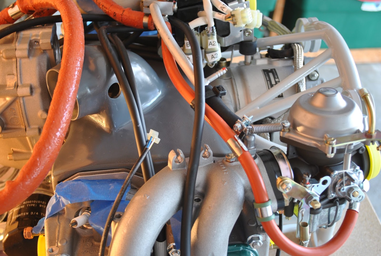
I started by removing the springs and the carburetors one by one.  I removed the fuel line clamps and removed the carburetor flanges and installed the drip pans.  I reinstalled all of the components and reassembled the carburetors.  It was pretty straight forward and went well.  I was able to reinstall the carburetors and torque them to the correct values.
Next I worked on the fuel system.  I removed the Banjo Bolts from the top and bottom of the camp block on the compensating tube assembly.  I removed the hose nipple and put it in a plastic bag for safekeeping.  I also removed the fuel jet from the M8x1x17 Banjo Bolt as instructed.  I loosened the clamp block and rotated it 180o on the tube.  I reinstalled the M8x1x27 Banjo Bolt and in attempting to torque  it to the correct value I twisted the bolt in half.  Rats!  I ordered an new bolt from  California Power Systems.  It will be here next Tuesday.
I will have to wait until then to install the fuel hoses to the bottom of the clamp block. 
I then started with the installation of the engine.  I started by bolting and drilling the lower engine mounting bolts through the nose gear upper attachment assembly.  I but an AN3 bolt in the hole on the right side and final drilled the hole on the left to 3/8" dia.  I installed the AN6 bolt with the male rubber washer and steel washer and tightened them with a nut.  I then removed theAN3 bolt from the hole on the right and final drilled the hole 3/8" dia.  I installed the correct AN6 bolt in the hole.  I removed the rubber and steel washers from the left bolt.    
I attached a nylon sling to the prop shaft and passed it through the engine mount ring.  
Using a come-along attached to an eye-hook I screwed into the beam in the garage I hoisted the engine off of the work table. 
I pushed the fuselage into the garage.  By adjusting the engine up or down with the hoist I was able to get it to the right elevation to install the mounting bolts and hardware.  I was able to install the bolts without too much trouble.  I will need to have Arlene help me torque the lower bolts.  I will need to have her hold the bolts inside of the cockpit while I work on them from the engine side.  
The engine in now hanging on the air frame.

Thursday, March 14, 2013

Install Intake Manifolds and Prep Drip Pans

It was good to get back to work after a long, bitter cold and complicated winter.  I cleaned and swept the garage and pulled the engine building cart out.  I uncovered the engine and found everything to be in great shape.  Just as I left it in January.
I bolted the intake manifolds in place.  I checked to make sure the O rings were properly seated and installed the bolts.  I torqued them to the proper inch pounds. I tightened the spark plugs and installed the leads.  
I reinstalled the ignition module and tightened the bolt and nut.
Next I located the drip pans.  I removed the blue vinyl film and deburred the edges.  I used the countersink tool to prep the holes for the rivets.  After installing the rivets at the corners I mixed some Pre Seal and filled the corners and sealed the seams.

Thursday, January 31, 2013

Wing Spar Alignment Tool

John Peck's alignment tool
The wing spar alignment tool I had fabricated
Using a picture posted by John Peck in his build log I had a wing spar alignment tool fabricated by a local machine shop.  I took one of the spar pins and a picture of John Pecks alignment tool to Loveridge Machine in SLC and had them fabricate the tool for me.  It took a couple of days.
I  am sure it will do the job the next time I install the wings.

Friday, January 4, 2013

Warm The Engine and Install Cooling Shroud

Yesterday I decided I need to do something about the cold temperatures and working on the engine.  The next step is to install the cooling shroud on top of the engine case.  It is attached with RTV silicone.  It needs to be warm for this to work.  I decided to install a 150 Watt light bulb under the box covering the engine.  This way, the heat from the bulb will warm the engine and the space under the box.  I drilled a hole in the top of the box at one end and threaded the wires from a light socket through the hole.  I attached a plug end so I can attach a drop cord to make it work.  I put a bulb in the socket and attached the cord.
By putting moving pads over the box it retains the heat and gets nice and warm inside.  I plugged in the light this morning when I left for work.  Upon my return home about 1:00 pm the engine had warmed.  Since the temperature has been in the single digits for the last few days, that was a nice surprise.
I applied a bead of gray RTV along the outline of the shroud.  I then pushed the shroud down over the cooling fins on the cylinders and made sure it contacted the RTV.  I used a popsicle stick to make sure there are no voids along the edge of the cooling shroud.  There were a couple of places I had to add some additional material, but all in all, it worked really well.  I have attempted to get some photos of the shroud in place. For my next trick I will begin re-installing the cooling system over the top of the cooling shroud.