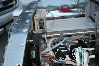
I also removed the upper fuselage skin and proceeded to work on
the wiring. I installed the WH-00063 Firewall
Forward Wiring Harness 25-pin sub D connector to the control module. I then routed the wires past the cushioned
clamp next to the cooling fan and out the firewall grommet. I could not get the harness into the
cushioned clamp so I used a wire tie to connect it to the clamp. I also
attached the WH-00062 power wiring harness to the rear of the Power and Switch
module and routed the wires thru the fire grommet. I wire tied the power wires to the bundle of
wires going past the Com Supports I put
a clam shell on the EGT 25-pin sub D connector and attached it to the RV-12 EGT
Exhaust Gas Temp Wiring Harness and routed the wires thru the wire tie holding
the bundle to the cushioned clamp and out the firewall grommet.
It is really tight quarters in the instrument shelf area and I am
having trouble routing these new harnesses thru the existing cushioned clamps
and snap bushings. I am holding the harnesses
in place by wire tying them to other wires running in the same areas.
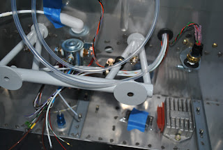
I cut a 4" length of PT ¼" ID tube and inserted one end
of the ¼" heat resistant tubing for the pitot. I cut the ¼" pitot tube from the
fuselage and inserted the end into the splice tube. I routed the pitot tube thru the grommet in the
firewall. I coiled it around the GPS
antenna shelf. I also routed the wires
from the wiring harnesses
I inserted the white wires and yellow wire with the
spade connectors into the Connector Housing for the Rectifier Regulator. They snapped into place and a gentle tug
assured they were properly seated. I
plugged the connector into the rectifier.
That's all for today.


