Thursday, January 31, 2013

Wing Spar Alignment Tool

John Peck's alignment tool
The wing spar alignment tool I had fabricated
Using a picture posted by John Peck in his build log I had a wing spar alignment tool fabricated by a local machine shop.  I took one of the spar pins and a picture of John Pecks alignment tool to Loveridge Machine in SLC and had them fabricate the tool for me.  It took a couple of days.
I  am sure it will do the job the next time I install the wings.

Friday, January 4, 2013

Warm The Engine and Install Cooling Shroud

Yesterday I decided I need to do something about the cold temperatures and working on the engine.  The next step is to install the cooling shroud on top of the engine case.  It is attached with RTV silicone.  It needs to be warm for this to work.  I decided to install a 150 Watt light bulb under the box covering the engine.  This way, the heat from the bulb will warm the engine and the space under the box.  I drilled a hole in the top of the box at one end and threaded the wires from a light socket through the hole.  I attached a plug end so I can attach a drop cord to make it work.  I put a bulb in the socket and attached the cord.
By putting moving pads over the box it retains the heat and gets nice and warm inside.  I plugged in the light this morning when I left for work.  Upon my return home about 1:00 pm the engine had warmed.  Since the temperature has been in the single digits for the last few days, that was a nice surprise.
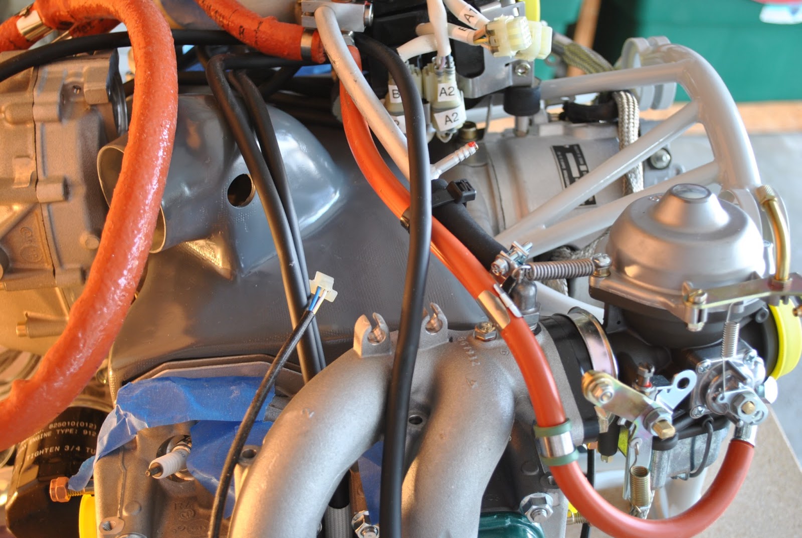
I applied a bead of gray RTV along the outline of the shroud.  I then pushed the shroud down over the cooling fins on the cylinders and made sure it contacted the RTV.  I used a popsicle stick to make sure there are no voids along the edge of the cooling shroud.  There were a couple of places I had to add some additional material, but all in all, it worked really well.  I have attempted to get some photos of the shroud in place. For my next trick I will begin re-installing the cooling system over the top of the cooling shroud.

Thursday, December 27, 2012

Engine Mounting Ring

This afternoon I installed the engine mounting ring on the Rotax.  First, I uncovered the engine and set the cooling shroud in place.  It think it will look good.
I then proceeded to install the engine mounting ring on the engine.  To begin with I removed the front bolts from the engine support angles.  I lifted the rear of the engine and placed a 2x4 block under the crank case.  I then used a small pair of channel locks to remove the 4-spring clamps from the water pump inlet and outlet on the water pump.  After cleaning up the coolant that drained from the hoses I proceeded to install the engine mount.  I placed tape on the legs of the engine mount to avoid scratching the powder coat as instructed.  As I began installing the mount it became obvious that I was not going to be able to get it in place without removing the electronics module mounting bracket I was not able to remove earlier.  By holding the metal end of the rubber shock absorber I was able to remove the bracket and attach it to the module.  With the bracket out of the way I was able to rotate the engine mount ring into place and make the attachment to the engine.  I had to go on line to look up the Rotax Illustrated Parts Catalog so I could find the torque values for the bolts holding the engine mount in place.  The bolts are to be torque to 30 ft. lbs.  After the engine mount was installed I put the 2x4 block under the front of the engine and clamped the ring down to the table to give the engine some stability.

Wednesday, December 26, 2012

Paint Cooling Shroud

This evening I finished cleaning up the cooling shroud and applied a coat of gray primer.  High heat type.  After allowing it to dry I applied a coat of dark gray finish paint on the cooling shroud.  It will look good I hope.

Friday, December 21, 2012

Engine Cooling Shroud

This has been a very difficult month to say the least.  On December 4th our daughter, Kerri, had major oral surgery.  The procedures she underwent were performed by and ENT Dr. and an oral surgeon.    They fixed a deviated septum, performed a UPP (remove the uvula and remove a portion of the soft pallet, cut a small window in her chin and pulled her tongue forward 4 mm and cut and removed a wedge out of her tongue and stitched it back together.  She was in the Shock Trauma ICU for 10 days and in Adult ICU for 3-more days.  I spent every afternoon and evening visiting her.  She is now home and well on the road to recovery.  This afternoon I was able to work on the airplane again.
 It is pretty cold outside, but the sun was shining so I set up on the driveway.  Last week I received and inventoried the landing gear SB modification kit from Vans.  I will begin making the necessary mods soon. 
Today I worked on the engine cooling shroud.  I had marked the shroud previously so I started to remove the excess fiberglass to the scribe lines.  After removing the bulk of the material I slipped it in place on the engine.  I used my Dremel tool and a cutting disc to cut the fiberglass.  The fit was pretty good, but it could be better.  I used the Dremel tool with a small sanding drum to remove the fiberglass material to the scribe lines.  I put it back on the engine and the fit was considerably better, but not good enough.  I used a Sharpie to mark some places that needed additional work.  After cutting out some material to clear the cylinder fins on one end and removing a small section from the rear of the shroud it fits pretty good.

I also drilled a ¾" hole for the flexible tube that will provide cooling to the rectifier.  I also used a Sharpie and a pencil to mark the top of the engine for the RTV that will be used to install the shroud.